メインコンテンツにスキップ

初代Mac ProはIntel Xeonをベースにしたワークステーションコンピューターです。初代モデルには2006年から2008年のデバイスも含まれます。

317回答 すべてを表示

Bluetooth module connector type

Hi!

Can anyone tell me what the connector on the short cable is called that connects the Mac Pro 4,1's mainboard to the bluetooth module to deliver the USB signal (mainboard side)? And which two of the four pins hold the USB signal? Is this a common type of connector or an Apple custom thing?

I'd like to replace the Wifi module with a newer Wifi / BT LE module from an iMac, and it needs a USB signal, which I should be able to get from the original bluetooth module connector. But I don't want to destroy the original cable.

Block Image

Thanks in advance!

Timo

回答がありました! 回答を表示 同じ問題があります

この質問は役に立ちましたか?

スコア 2
4 件のコメント

In case anybody is ever interested, the connector is called JST GH.

さんによる

Could you post a photo where we can actually see that end?

さんによる

The photo is in the first post. Or do you mean the connector on the mainboard?

さんによる

Shouldn't you just need a 3rd party WiFi/BT card that is compatible with the Mac Pro? Then you could just use this guide: http://meanderingpassage.com/2007/07/18/...

さんによる

コメントを追加

6件の回答

ベストアンサー

You know I looked at this question a couple of weeks ago and it didn't make sense to me. That bluetooth is built into the airport card that goes into the slot on the logic board and that cable threw me off.

Here's the part you need:

http://www.ebay.com/itm/like/18189431769...

That cable looks like a power cable for a PCI video card.

@danj knows more about the airport bluetooth upgrades than I do, let's see if he will chime in as to which one to install.

このアンサーは役に立ちましたか?

スコア 2

3 件のコメント:

The link no longer works, any chance you can provide what the connector is called?

さんによる

The article you link to, then links to cables that will supposedly work for sale on eBay, unfortunately, the vendor is all out of the 4-pin cables. I have searched for these online to no avail. I wound up ordering what is suppose to work, some JST 4 pin GH connectors but they have an extra bit of plastic on them and will not fit, I've tried to file the extra plastic off, but then when you do this, it winds up breaking then the wires run free. The connector is really nothing like the one that came out of the mac. I've now purchased the JST GH connectors from 3 different vendors online and nothing so far seems to fit or work. Surely someone knows what that plug is called so one can do a google search for it and find it. It does not seem to be the JST GH connector as others have stated.

さんによる

コメントを追加
最も参考になった回答

I found this is a MacPro upgrade group on a different platform:

The USB header on the logic board uses a Molex PicoBlade connector.

manufacturer link:

https://www.molex.com/molex/products/fam...

retail link: 15 PCS 4 PIN 1.25mm Female Connector on One Side - 150mm 1571 28 AWG & 15 PCS 4 PIN 1.25mm Male Connector https://www.amazon.com/dp/B07HLF2MFJ/ref...

このアンサーは役に立ちましたか?

スコア 3

1件のコメント:

Thank you!

FYI for others: you may need some heat shrink tubing to splice the other end of the wires into your cable your matching it up with; if you don't already have some on hand.

Here's another option with comes with this exact plug and the wires to install in it (simply plug them in). I found a similar product on Amazon:

https://www.amazon.com/gp/product/B07S18...

It comes with more plugs (and extras of other sizes), extra wires, and some heat shrink for splicing the other end neatly. it costs more, but will allow me to choose colors of the wire that go into the plug, plus also have other extra sizes of similar plugs if needed for future projects. only about $5-6 more for a neat little kit and some extra materials.

I just ordered it. I'll update to let you know how it works.

さんによる

コメントを追加

As I said in an earlier answer, the connector is called JST GH, so the problem is solved for me.

To elaborate on the original problem:

The available AirPort cards for the Mac Pro don't support 802.11ac, and the Bluetooth modules don't support BT LE, which means they are also incompatible with macOS' handoff features.

The solution is to replace the original AirPort card with a combined Airport/BT card from an iMac via an additional adapter. The original BT connector on the Mac Pro will stay empty, but on the Mac Pro 4,1 / 5,1 you need to deliver an USB signal to the adapter. If you don't want to route a cable from an external USB port back to the inside or have an internal USB port on a PCIe card, you can use the original BT connector on the mainboard to provide the USB signal via a selfmade cable.

Since I didn't want to destroy the original cable, I was looking for the name of the connector for the new cable.

このアンサーは役に立ちましたか?

スコア 1

2 件のコメント:

I ordered a 4 pin JST GH connector cable for my 4,1 mac pro, it was not wide enough, it seems you can only find 1.25mm which is what I bought, but too small. can you provide anything more specific on what is needed to connect to the motherboard or logic board?

さんによる

If you look closely on the plug (with a magnifying glass, or take a pic and zoom in) it says on it "H JST" & "6U-B." Also, It is a 6-pin plug, not 4. The bluetooth module only uses 4 wires/4 pins, but it is a 6-pin plug, with 2 spaces left empty.

EDIT: Oops, My bad! it is a 4-pin connection on the Motherboard interface. the other end of the wire (connecting to original BT Card) is a 6-pin. I got mixed up thinking they were both 4pin. Sorry.

My MacPro is a 5,1 (2010)

さんによる

コメントを追加

I know that this is an old thread but having gone (and seen others go) through a labyrinthine maze of conflicting advice and inadequately-described parts, I wanted to share my research with others who may find themselves in the same situation. The JST GH connectors are not the correct connector, as Alan Miller pointed out above. I wound up getting the design drawings for the JST and comparing them with Apple’s bluetooth connector.

The bluetooth header on the backplanes of classic 4,1 and 5,1 Mac Pros is a Molex PicoBlade 4-circuit, 1.25mm-pitch header. A perfect cable (black wires, 12" long with the appropriate PicoBlade connector) can be obtained from Digi-Key (Part # WM15259-ND) for about $3.61 as of this writing. The Molex part number for this cable is: 0151340403

I used it to save over $100 by buying my BCM94360CD for about $35, the cable for $3.61 and an antenna for $18, rather than the kits that currently range from $120 - $215.

このアンサーは役に立ちましたか?

スコア 1

2 件のコメント:

Here's the Link to buy from DigiKey:

https://www.digikey.com/en/products/deta...

さんによる

Here's the Link to Molex item, Part # 151340403:

https://www.molex.com/molex/products/par...

さんによる

コメントを追加

This isn't an answer, but a continuation of the original Question:

I am still trying to solve this problem myself. I apologize for all of my "thinking out loud" posts above while I was trying to figure this all out myself. I should have read all the comments and links first before I began commenting! Forgive me, I'm a newb, lol!

I found and ordered an appropriate plug based on the answers above. Thank you all for providing the info to help find that! I was originally just going to cut and splice into the factory wire. I am waiting on the plug to arrive. But, I still need to know how to splice it onto my new BT module's cable. I don't how to match up the wires/pins from my new BT Module's cable to the port/socket/plug on the motherboard. Both have 4 wires. I'd assume they'd have the same function, but I am not sure if they are in the same order. Can anyone help me answer this so that I don't mess it up when splicing it? Does anyone know the pin line up of the socket this wire plugs into on the motherboard?

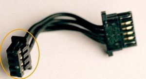
The Pins are labeled on the original Apple BT card, where the connection goes in (6-pin side), but not anywhere on the other end where the 4-pin connects to the motherboard. Also, I don't know what the labels stand for. Also worth noting, the pins in the plug, on the BT card's side, are in a different order than the pins in the plug on the motherboard side. Yes, the 4 wires are actually crossed b/w the two plugs. I really don't understand why they would have done this?!

Here the labels I've found, in case anyone can decipher them for me/us. Thank you in advance!

From top to bottom (only the middle 4 of the 6 pins are actually used) on MacPro original BT card:

Pin 2: D2 (1st wire on 6-pin side: corresponds to 3rd wire on the 4-pin plug)

Pin 3: D4 (2nd wire on 6-pin side: corresponds to 1st wire on the 4-pin plug)

Pin 4: D3 (3rd wire on 6-pin side: corresponds to 2nd wire on the 4-pin plug)

Pin 5: R15 (4th wire on 6-pin side: corresponds to 4th wire on the 4-pin plug)

(The 2 unused pins are also labeled: Top Pin 1: D5, Bottom Pin 6: D8)

Does D stand for Data and R for Radio?

This is BCM92046MD Card. I guess I could do a search for the pin layout of that part #. I will update if that yields valuable results.

Since I'm going to splice the 4-pin plug onto the 4 wires from my new BT card, I've got to get the wires matched up in the correct order, based on their function. But, I don't know their function to begin with, on either end!

The 4 wires from my new BT card are currently housed in a supposedly 'standard' 9-pin internal USB interface with 4 wires/pins being used. Although, I have seen some other versions only using 2 wires, and not all 4. I went with a PCI-e slot wifi bt card, rather than using the original stock location (which i think is a mini PCI-e bus?), for the sake of having external antennas & mistakenly thinking it would be an easier install. I did not realize the BT connection it came with would be incompatible. It is either Fenvi Model # FV-A436CD or Fenvi Model # FV-946CD. The model # listed on eBay and the #s/images on Fenvi website don't match up accordingly.

Link to the WiFi/BT card I bought: eBay Item # 392847805752

The seller told me the pinout for that cable is standard for USB 9 pin cables.

Top to Bottom:

VCC (Red)

Data- (White)

Data+ (Yellow)

GND Empty (Black/Green)

How do I match up this new BT card's 4 wires to the existing original BT plug/socket on the 2010 MacPro's motherboard?

Does anyone know how the new wires would coordinate with the existing socket?

Is it even possible to determine this from the pin labelings on the original BT card?

Thank you for any help/advice you all can provide me!

Andy will be eternally Grateful!

このアンサーは役に立ちましたか?

スコア 0
コメントを追加

Perhaps THIS MACRUMORS THREAD will help.

このアンサーは役に立ちましたか?

スコア 0

2 件のコメント:

yes and no. Unfortunately, every blog and forum I've found are discussing similar cards to what I bought but have a BT cable with 2 wires (data- & data+). My new BT card's cable has 4 wires. I have been able to found out that the top two pins on the MacPro Motherboard BT Socket are for Data, but I still can't find a definitive answer as to what exactly the other two are for. assumedly they're for power. But, I need to know which would be used for VCC and which for GND. Not anyone is saying this, because all anyone else is concerned about are the 2 wires for data. I don't know why I had to pick the oddball card that has 4!

さんによる

FYI - I can confirm that the pinout on my 5,1 for the JA120 Bluetooth connector goes like this from top to bottom:

1. D- (This is the top most pin and has a little triangle silkscreen next to it)

2. D+

3. VCC

4. GND (Bottom most pin towards the bottom of the chassis.

I connected a small four-port USB hub to the internal Bluetooth connector in order to provide internal USB ports for a Titan Ridge Thunderbolt card. It works surprisingly well!

さんによる

コメントを追加

回答を追加する

Timo Moretto さん、ありがとうございました!
統計データ:

過去 24時間: 2

過去 7 日: 10

過去 30 日: 36

今までの合計 3,451