はじめに
The Xbox Elite Wireless Controller Series 2, launched on November 4, 2019.
Building on the success of the original Elite controller, this second-generation model includes adjustable-tension thumb sticks, redesigned rubberised grips, remappable rear paddles and shorter hair-trigger locks.
It supports up to 40 hours of battery life per charge and features Bluetooth connectivity, making it compatible with both Xbox consoles and PCs.
This controller does tend to have more issues compared to the original Xbox Controller. Common issues including buttons sticking/not registering, stick drift and/or sticks not centering.
必要な工具と部品
-
-
Grab that trusty plastic pry tool and start popping off the faceplate. Begin at the top near the bumpers and work down each grip—like peeling a banana, but way cooler.. You may like to remove the magnetic thumb sticks for more clearance.
-
The clips are quite sturdy and you shouldn't be afraid to be firm with removing the faceplate to dislodge the clips. Give it a good, firm push to dislodge them. There are four clips down each grip and there is also dampening tape which isnt an IP requirement and wont need replacing.
-
-
-
The joysticks are screwed onto the potentiometers and are very tight, probably more secure than your grip after a long gaming session.
-
Don’t get tricked by that tempting screw in plain sight—that’s a tensioning screw. You will need to turn the joystick counter clockwise to remove using either the thumbstick or a pair of pliers.
-
Note: If you are reusing the joysticks be careful not to let the pliers slip and damage the thumbstick mounting grooves.
-
-
-
Remove the 6 x T-8 Security Torx Screws holding the front and back together. The Red circled screw will have a white sticker over it, if the sticker’s missing, someone else has already peeked inside—maybe looking for buried treasure.
-
Good news! All the screws are the same length and you do not need to remember positions. Once the screws have been removed you will be able to lever near the bottom of the grips to remove the back of the controller (red arrow)
-
-
-
-
There are two tabs holding the centre bar between bumpers in place. Using a small blade pop these upwards to remove space up the centre bar.
-
There are also two tabs on either end of the RB and LB bumpers facing outwards marked with a yellow circle. Remove one end by lifting the slotted tab off the pin and the other end should be free to slide off. Boom—you’re officially breaking down barriers, one bumper at a time.
-
-
-
Time to play “peek-a-boo” with the motherboard! Peel back tape covering the connection on the motherboard. While holding the tape back use a small plastic blade too dislodge the connections, these pop upwards like a shirt clip button.
-
-
-
Now, for the serious stuff—There are four solder points on the left and right that can be de-soldered depending on what is required during a repair. The temperature required to remove is approx 450 degrees C.
-
If you arent removing the solder be careful while removing the motherboard in this step.
-
Remove the 2 T6 Torx screws (yellow circle) and gently slide the motherboard up along the two dowel pins (red circle). The motherboard (green) can now be repositioned away from the daughterboard(blue).
-
The black and grey wires are looped through the plastic tabs on either end as well as around the front of the plastic panel (yellow circle), removing them from here can allow more free room without de-soldering.
-
The headphone jack can now also be removed (red square)
-
-
-
Remove the T-6 Torx screws from each trigger button.
-
Almost there! There’s a tiny latch on each trigger that you can lever outwards, allowing you to pop the trigger and motor assembly free from the case. And then the motors can be separated from the trigger case
-
-
-
Remove the 4 T-6 Torx screws (yellow circles) holding down the daughterboard.
-
Slide the daughterboard up along the dowel pin in the bottom left corner (red circle).
-
The remaining buttons will also become dislodged during this stage. Once removed you will be able to see the unique mounting locations of the buttons which stop incorrect fitment of the buttons during assembly—so no accidental “A” where the “X” should be.
-
-
-
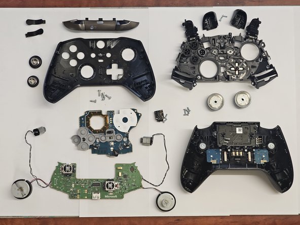
And that’s it! You’ve made it to the end of your epic teardown. Hopefully this teardown has allowed you to reach the components that require replacement or cleaning!
-
-
-
Rear Casing - Showing trigger stops and rear paddle hardware
-
Inner Casing - Showing grooves of buttons to stop incorrect fitment
-
MCU - BGA IC Responsible for WiFi and Bluetooth Connectivity (Red Square)
-