はじめに
This guide will run through how to teardown a wireless charging pad. It is quite simple and doesn't take much time at all. Enjoy!
必要な工具と部品
-
-
First thing to do is remove the pad that covers the screws. This is what the phone sits on when charging (on top of device).
-
Use a spudger or some other kind of flat tool you can pry under the padding with to loosen the adhesive and pry off.
-
Pry gently as you don't want to rip or tear this padding. NOTE: It is only held on with a sticky adhesive tape.
-
-
-
Once you have removed the padding ring you will notice (4) phillip head screws.
-
Use a small screwdriver to remove these screws. (I used a #1.2 phillip head screwdriver).
-
Once the screws are removed you should be able to remove the bottom cover of the device exposing the circuit board.
-
-
-
Once you have the bottom cover off you can access the circuit board and charging unit.
-
To access the top of the charging unit just pry away the top cover and the piece the circuit board is connected to.
-
-
-
-
To remove circuit board: There are two clips holding the board in place (see photo 1). Using a spudger or a flat tool pry one of the clips away while lifting up on that end of the board. Once the board clears the clip the board will come out.
-
To remove charging unit: The charging unit is held in by adhesive and connected to the circuit board (see photo 3). Just pry from adhesive.
-
-
-
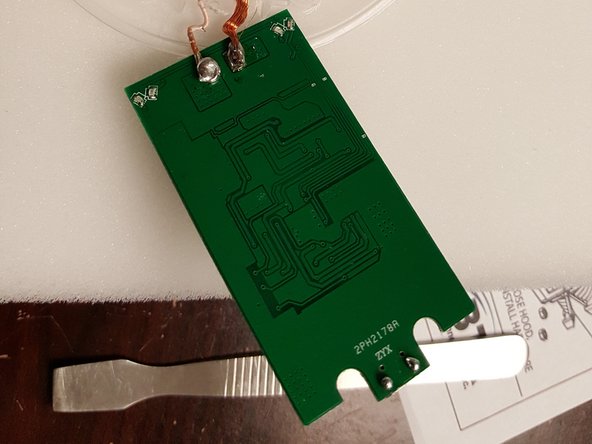
Whether replacing circuit board or charging unit... Any work done here will have to be soldered.
-
The charging unit is soldered to the back of the circuit board. (see photo)
-


6 件のコメント
If you don't like the beep, disable the speaker. If the speaker is surface mounted it can't be easily disconnected. Use a drop or two of superglue inside to silence it.
harryhouck - 返信
this is for the fake one, what about the original one? it doesnt have this screws
Ditto that fake
It’s fake ditto