はじめに
In this guide we'll see how to get to the the console's main board.
必要な工具と部品
-
-
Remove the 6 screws with a 4.5mm Gamebit screwdriver from the back of the unit.
-
Turn the unit back up and lift the top cover. You can now admire :
-
The ejecting mechanism.
-
The sound chip. Present on early models, this is the main difference with the later hardware revisions of the console.
-
The main board shield.
-
The capacitors guard.
-
-
-
The mechanism is held back in place by a small spring. It's not too tense but be careful not to lose it. Also, note how it's placed for future reassembly.
-
Remove the mechanism by slightly lifting the axle from the right and pulling it out.
-
-
-
We'll need to remove a couple screws with a Phillips #2 screwdriver.
-
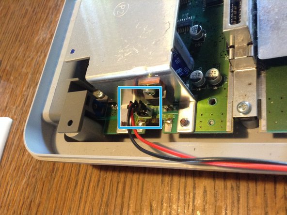
It's plugged to the main board with a small plastic socket. Simply pull on it to set it apart.
-
-
-
-
The front panel is connected to the main board with a ribbon cable. Gently pull it out of its socket.
-
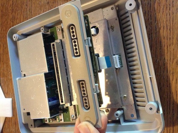
The front panel can then be lifted out.
-
-
-
The chip is held by 2 Philips #2 screws.
-
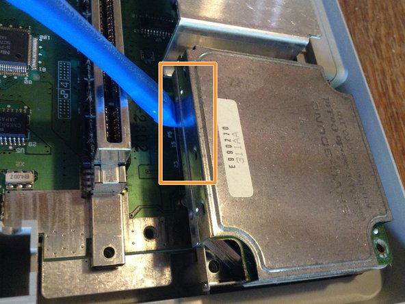
It's then just held by the bus socket on the lower left side of the chip.
-
Simply shimmy it out of the socket. You might need the help of a prying tool but don't put to much pressure on the cartridge port.
-
-
-
The board is now only held by 3 Philips #2 screws.
-
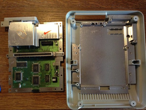
Lifting the main board reveals the lower shield that got scrapped in later hardware revisions of the console.
-
-
-
First, remove the lateral screw (Philips #2, still).
-
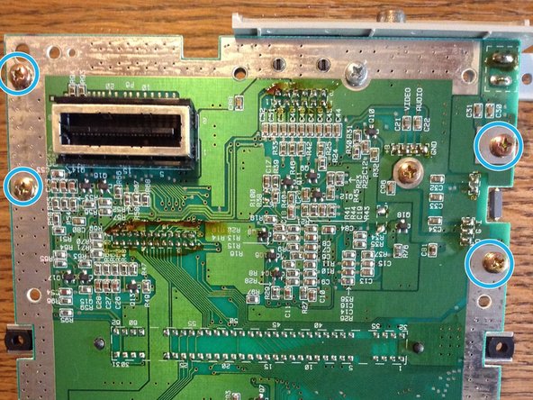
Turn the board around and unscrew the 4 last screws.
-


3 件のコメント
The innards of the Super Famicom are almost the same as the North American Super NES, you should be able to follow the SNES guides with the help of this teardown.