メインコンテンツにスキップ

この分解は修理ガイドでは ありません。 お持ちのDesktop PCを修理する際は、iFixitの修理ガイドをご利用ください。

  1. Microdigital TK 85 Teardown, The TK 85 case and connectors: 手順 1、 3の画像 1 Microdigital TK 85 Teardown, The TK 85 case and connectors: 手順 1、 3の画像 2 Microdigital TK 85 Teardown, The TK 85 case and connectors: 手順 1、 3の画像 3
    • 9V DC = Nomo P2 power supply

    • Expansão = Expansion connector 2x23 edge pins.

    • Joystick = Joystick connector DIN-6-07M.

    • Mic = audio output for a datacorder.

    • Ear = Audio input for a datacorder.

    • Video = RF chanel 3 VHF output.

  2. Microdigital TK 85 Teardown, Inside the TK85: 手順 2、 3の画像 1 Microdigital TK 85 Teardown, Inside the TK85: 手順 2、 3の画像 2 Microdigital TK 85 Teardown, Inside the TK85: 手順 2、 3の画像 3
    • Open it carefully because of the 2 keyboard flat cables.

    • Those flat cables are very problematic

  3. Microdigital TK 85 Teardown, Keyboard removed: 手順 3、 2の画像 1 Microdigital TK 85 Teardown, Keyboard removed: 手順 3、 2の画像 2
    • The upper part of the case is the keyboard, but the keyboard itself is not removable.

    • The lower part of the case is just a plastic part.

  4. Microdigital TK 85 Teardown, The circuit board: 手順 4、 2の画像 1 Microdigital TK 85 Teardown, The circuit board: 手順 4、 2の画像 2
    • The circuit board is a very compact circuit board with dual layer traks.

  5. Microdigital TK 85 Teardown, Rom and Ram: 手順 5、 2の画像 1 Microdigital TK 85 Teardown, Rom and Ram: 手順 5、 2の画像 2
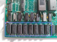
    • MM2716Q-5 => 16Kb Eprom

    • 52164KSF/N => 64kb Rom ? It is a custom Microdigital Rom compatible with the NMC2764.

    • MCM4116BC-15 => 8 x 16,348 bits Ram = 16Kb Ram

  6. Microdigital TK 85 Teardown, The RF generator: 手順 6、 3の画像 1 Microdigital TK 85 Teardown, The RF generator: 手順 6、 3の画像 2 Microdigital TK 85 Teardown, The RF generator: 手順 6、 3の画像 3
    • Just a RF Chanel 3 VHF modulator.

  7. Microdigital TK 85 Teardown, Microchips identification: 手順 7、 2の画像 1 Microdigital TK 85 Teardown, Microchips identification: 手順 7、 2の画像 2
    • Microprocessor

    • Rom

    • Eprom

    • Ram

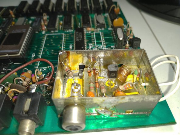
    • Oscilator 555. Works as an PWM 5 Volt power supply to the micropocessor.

    • Spare space for an audio integrated circuit. It was never implemented in producion in this model.

    • Voltage regulator 7805

    • Frequency divider = 6,5Mhz used for video and 3,25Mhz used for actual clock.

作成者

2人の作成者と共同で作成されました。

Vinicius Rodrigues Bellini

メンバー登録日: 12/12/22

1,046 ポイント

6のガイドは作成済み

0 件のコメント

コメントを追加

統計データ:

過去 24時間: 1

過去 7 日: 12

過去 30 日: 21

今までの合計 1,081