メインコンテンツにスキップ

必要な工具と部品

この分解は修理ガイドでは ありません。 お持ちのMacintosh IIsiを修理する際は、iFixitの修理ガイドをご利用ください。

  1. Macintosh IIsi Teardown, Top Case: 手順 1、 2の画像 1 Macintosh IIsi Teardown, Top Case: 手順 1、 2の画像 2
    • Start by turning the computer around, and remove this #0 Phillips Screw.

    • There may or may not be a Phillips #0 screw here, depending on whether or not the computer has ever been serviced.

  2. Macintosh IIsi Teardown: 手順 2、 3の画像 1 Macintosh IIsi Teardown: 手順 2、 3の画像 2 Macintosh IIsi Teardown: 手順 2、 3の画像 3
    • Now lift these two clips, and slowly pivot the case up.

    • You can now seperate the top of the computer from the rest of the machine.

  3. Macintosh IIsi Teardown, Ram: 手順 3、 3の画像 1 Macintosh IIsi Teardown, Ram: 手順 3、 3の画像 2 Macintosh IIsi Teardown, Ram: 手順 3、 3の画像 3
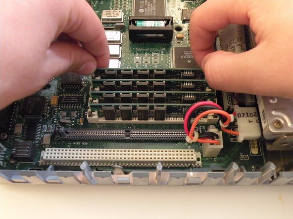
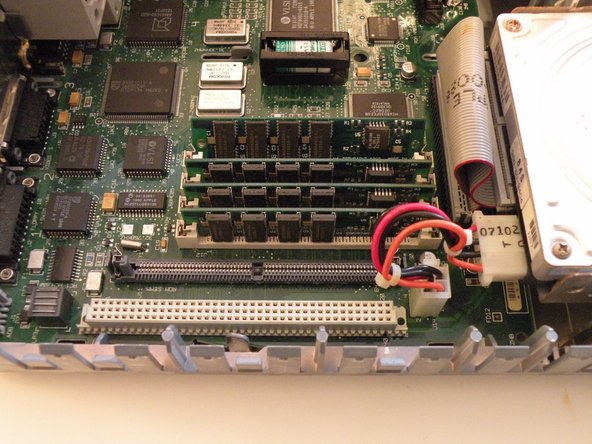
    • The IIsi uses 4 30-Pin SIMMs (Installed in pairs of 2) for a maximum ram capacity of 65MB. It has 1MB soldered to the logic board as well.

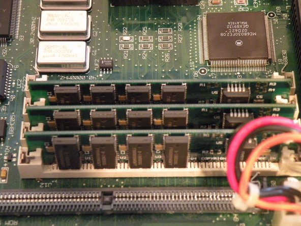
    • Start with this SIMM. Push these 2 metal tabs outward, then push the ram forward. It can then be lifted out. You have to remove the SIMMs in order, starting with the one you just removed. You can then work your way through all of them.

  4. Macintosh IIsi Teardown: 手順 4、 3の画像 1 Macintosh IIsi Teardown: 手順 4、 3の画像 2 Macintosh IIsi Teardown: 手順 4、 3の画像 3
    • 1st Photo: The RAM Module

  5. Macintosh IIsi Teardown, Hard Drive: 手順 5、 3の画像 1 Macintosh IIsi Teardown, Hard Drive: 手順 5、 3の画像 2 Macintosh IIsi Teardown, Hard Drive: 手順 5、 3の画像 3
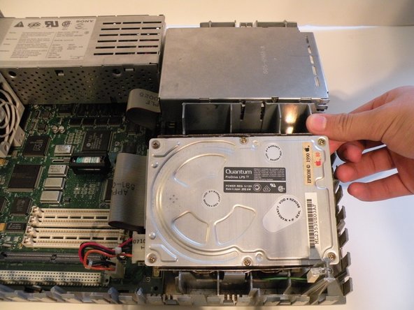
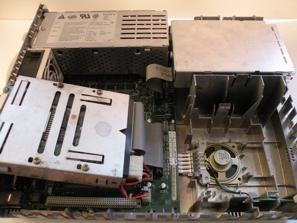
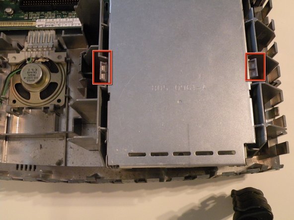
    • The Macintosh IIsi's hard drive is located ajacent to the ram and floppy drive.

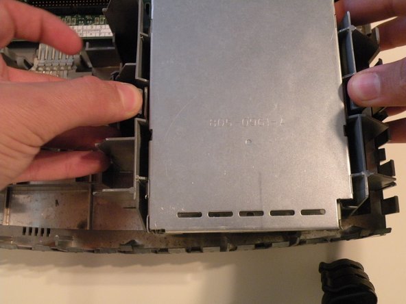
    • Start by pushing these two tabs out, and lifting the drive up.

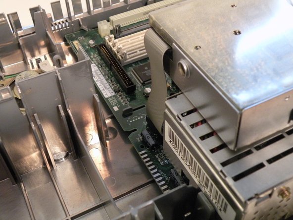
    • Then, flip the drive over, and remove the connection cables.

  6. Macintosh IIsi Teardown: 手順 6、 3の画像 1 Macintosh IIsi Teardown: 手順 6、 3の画像 2 Macintosh IIsi Teardown: 手順 6、 3の画像 3
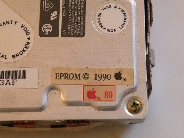
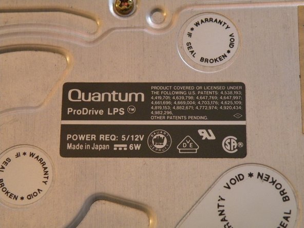
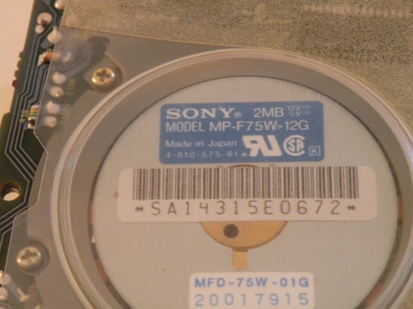
    • The hard drive: A Quantum ProDrive LPS, made in 1990, and surprisingly, it still works!

    • This drive has an 80MB capacity, not very large by today's standards, but not bad way back then...

    • Believe it or not, hard drive construction hasn't changed much in the last 20 years. Other than a few new interfaces, the form factor, 3.5" width and 4-Pin 12V/5V power connector has stayed the same.

  7. Macintosh IIsi Teardown, Floppy Drive: 手順 7、 3の画像 1 Macintosh IIsi Teardown, Floppy Drive: 手順 7、 3の画像 2 Macintosh IIsi Teardown, Floppy Drive: 手順 7、 3の画像 3
    • The "SuperDrive" is mounted similarly to the hard drive, and positioned right next to it.

    • Push these two tabs out, and lift the drive up.

  8. Macintosh IIsi Teardown: 手順 8、 3の画像 1 Macintosh IIsi Teardown: 手順 8、 3の画像 2 Macintosh IIsi Teardown: 手順 8、 3の画像 3
    • Flip the drive so it is on top of the power supply, and remove the "Red-Ribbon" cable.

    • 1.44MB floppy drives need a ribbon cable with a red stripe on one side. 400KB floppy drives use a ribbon cable with a yellow stripe on one side. 800KB floppy drives can use a red, or yellow striped cable.

    • This drive was manufactured by Sony in 1990.

  9. Macintosh IIsi Teardown, System Fan: 手順 9、 1の画像 1
    • The fan recieves power from two contacts on the logic board and has no connector.

  10. Macintosh IIsi Teardown: 手順 10、 3の画像 1 Macintosh IIsi Teardown: 手順 10、 3の画像 2 Macintosh IIsi Teardown: 手順 10、 3の画像 3
    • In all of the years that I have worked on this machine, I have found no good way to remove the fan.

    • The best way to start, is to push in here on the side of the fan.

    • Being careful not to exert too much force, try to push in, and wiggle the fan outward as such. (2nd Photo)

    • You can now lift the fan all the way out, and remove it.

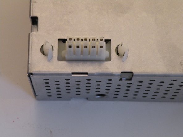
    • The Fan Power Contacts on the Logic Board:

  11. Macintosh IIsi Teardown, Power Supply: 手順 11、 2の画像 1 Macintosh IIsi Teardown, Power Supply: 手順 11、 2の画像 2
    • To remove the power supply, squeeze these two tabs and lift the front up.

    • On the back of the power supply, there is a tab that also must be pressed to remove the power supply fully. You can then lift it out all the way. A firm tug may be necessary to seperate the power connector.

  12. Macintosh IIsi Teardown: 手順 12、 2の画像 1 Macintosh IIsi Teardown: 手順 12、 2の画像 2
    • Information on the power supply:

    • It was made by Sony in 1990, and uses a 10-Pin power connector.

  13. Macintosh IIsi Teardown, Logic Board: 手順 13、 3の画像 1 Macintosh IIsi Teardown, Logic Board: 手順 13、 3の画像 2 Macintosh IIsi Teardown, Logic Board: 手順 13、 3の画像 3
    • The logic board is designed in a way, where it can be slid forward, then lifted out.

    • To remove the board, push these two tabs outward, and begin to slide the logic board away from the back (Port Side) of the computer.

    • Once the logic board clears the ports it can be lifted out.

  14. Macintosh IIsi Teardown: 手順 14、 1の画像 1
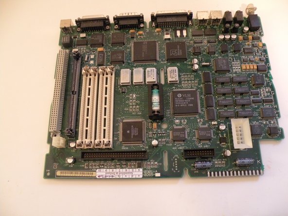
    • The Processor: 20Mhz Motorola 68030 model # MC68030RC20B

    • The Onboard RAM: 1MB Soldered the the logic board.

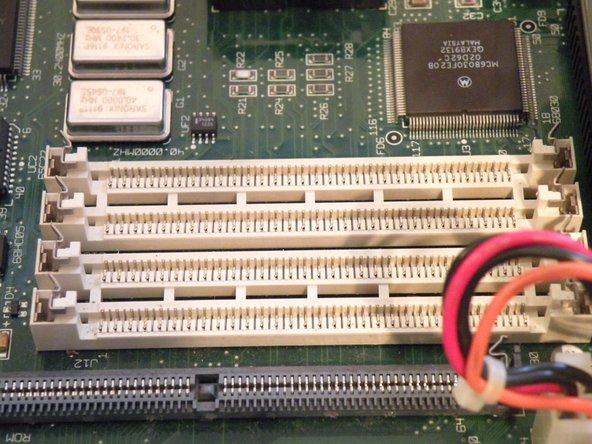
    • RAM Slots: 4 30-Pin DIMMs installed in pairs.

    • ROM SIMM Slot: If your computer doesn't have one if these (and it works) , it doesn't need one. If it has one, it needs it in order to boot.

    • PDS Slot: For Attaching a riser card containing a math co-processor. A PDS card can then be plugged into the riser card. PDS - Processor Direct Slot

    • Power Supply Connector: for direct connection to the power supply.

    • "VSLI" chip: This machine's equivalent of a "Northbridge" It manages RAM, PDS, and the external ports.

  15. Macintosh IIsi Teardown, Macintosh IIsi Teardown: 手順 15、 2の画像 1 Macintosh IIsi Teardown, Macintosh IIsi Teardown: 手順 15、 2の画像 2
    • The Macintosh IIsi, in pieces.

作成者

2人の作成者と共同で作成されました。

Chris Green

メンバー登録日: 10/11/09

36,978 ポイント

49のガイドは作成済み

チーム

Master Techs Master Techs人のメンバー

Community

322 メンバー

2,521のガイドは作成済み

0 件のコメント

コメントを追加

統計データ:

過去 24時間: 1

過去 7 日: 2

過去 30 日: 5

今までの合計 7,853