はじめに
How to take apart the M6013 Capacitor Meter
必要な工具と部品
-
-
-
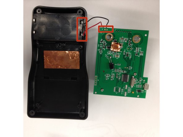
Remove circled screws
-
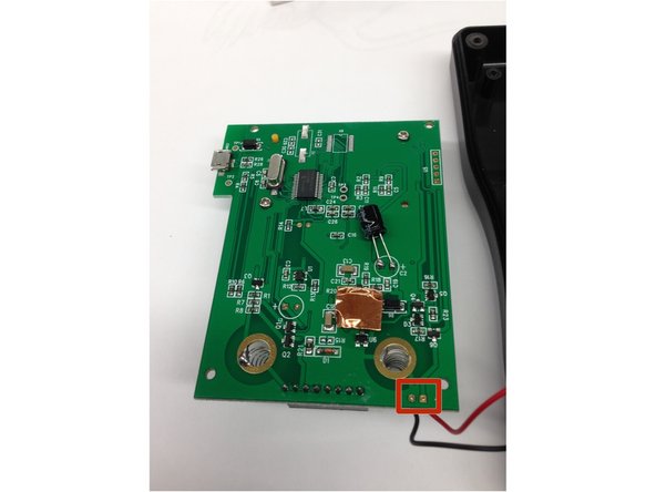
Unsolder the square locations either on the circuit board or the case to fully remove the circuit board
-


チーム

Cal Poly, Team 16-56, Forte Fall 2012 Cal Poly, Team 16-56, Forte Fall 2012人のメンバー
CPSU-FORTE-F12S16G56
5 メンバー
13のガイドは作成済み