必要な工具と部品
-
-
First remove the back cover to expose the battery
-
Next pull the battery from the phone
-
-
-
Remove the white sticker to expose the black plastic tab that is covering the ZIF connector that is connecting the flex cable that goes between the motherboard and screen
-
-
-
Remove the black tab by first getting under it with something sharp like an exact knife
-
It's adhered with a weak adhesive and peels away easily
-
As you can see a hole was left open to specifically allow quick and easy mate/unmate of the ZIF connector
-
-
-
-
Unplug the ZIF (zero insertion force connector) by running a pair of blunt Tweezers underneath it. Twist and pull, this causes the black latch that's holding down the flex cable to open and then the flex cable can be pulled out of the ZIF with the Tweezers.
-
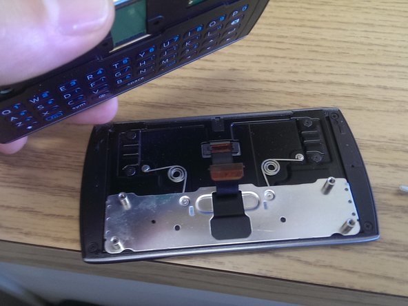
Since the screws were removed the phone's keyboard containing half can be lifted away from the screen.
-
-
-
Turn the phone so that the keyboard is facing you
-
The keyboard is flexible and can be peeled away from the body of the phone
-
The keyboard is latched in about 6 places and can peeled away slowly and carefully. It is not held down with adhesive.
-
-
-
Remove the 3 screws again using the Philips #0 screwdriver. This will allow you to pull out the motherboard from the back housing
-
-
-
The metal shielding was difficult to unscrew and the screws were all stripped in the process. Using a needle nose plier, the metal shielding was torn away
-
The exposed motherboard is shown here along with microscope pictures of the chips.
-
Chip #1
-
Chip #2: 1 GHz Qualcomm processor PM8058
-
-
-
Chip #3: Qualcomm CDMA antenna driver QTR8615
-
Chip #4: Samsung 2 GBit memory
-
Chips #5
-
-
-
After removing the motherboard the back housing can then be disassembled. The volume rocker and the power button slide out of the back housing without any effort
-
The upper antenna assembly is held in place only through a "snap into place" mechanism. It can be removed by apply a little prying pressure with end of a tweezer at the locations indicated with arrows
-
-
-
The lower antenna assembly can be similarly removed by applying a little pressure to pop it out of the assembly
-


2 件のコメント
You didnt describe how to disassemble the front panel with the touchscreen.
It would be useful to consider adding in the size of the screws removed, in case of misplacement. Also, since those screws tend to fall out over the course of normal phone usage