はじめに
You will learn how to tear down a Keithley 199 and learn what some of the parts inside are.
必要な工具と部品
-
-
This is the Keithley 199. The buttons on front are simply labelled with most having at least two functions. The display is NICE and bright even after 25 years. It's much brighter than it looks here.
-
This is the meter doing a two-wire resistance measurement on a 196K 0.01% resistor (with the test leads zero'd out). Thats a difference of 0.00255% from the listed value.
-
-
-
Here's the backside! You can see the GPIB connector on the right. The rear terminals on the left. The strange open port upper left is where you can connect the 8 additional channels for reading voltages (or 4 channels of 4-wire resistance readings).
-
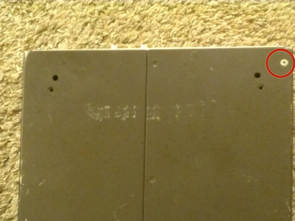
Remove the four screws and two "screw in threaded connectors" circled in red in the images.
-
The brown trim ring should come off easily.
-
-
-
Your device may or may not have the legs attached. Mine did not as it was likely rack mounted before. So in this case I only have two screws to remove.
-
Clearly the body of this device has seen better days. That being said it still runs like a champ. Oddly it has the word Apache written on the top-side. I wonder if it was used at some point to service Apache Helicopters.
-
Now the case should slide right off.
-
-
-
This is what the insides look like.
-
The yellow square is the digital logic board. It contains the GPIB circuits, the microcontroller and the EEPROMS which store the software.
-
The blue section is the power supply section which generate the multiple power rails.
-
The red section is the relay card with its eight high-speed high-voltage relays.
-
Lastly on the bottom we have the RFI/EMI shield. This shield protects the sensitive circuits from the effects of stray radiation.
-
-
-
-
Now it's time to remove the digital logic board.
-
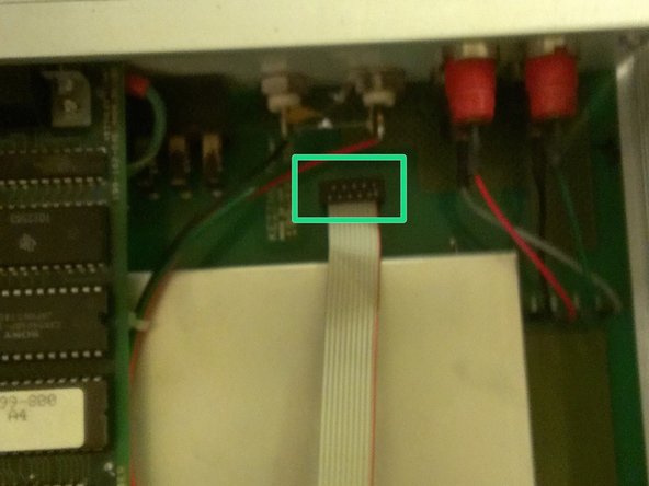
Remove the screw marked in red. The cable marked in blue (which I have already disconnected) and the cable marked in orange. Note: the cable in orange is oriented backwards from what you would expect based on where the cable goes. The yellow rectangle shows where the connector pins to the lower board are located.
-
Remove the side panel by removing all four screws.
-
Lastly, lift up on the logic board freeing it from the long pins that connect it to the main board.
-
-
-
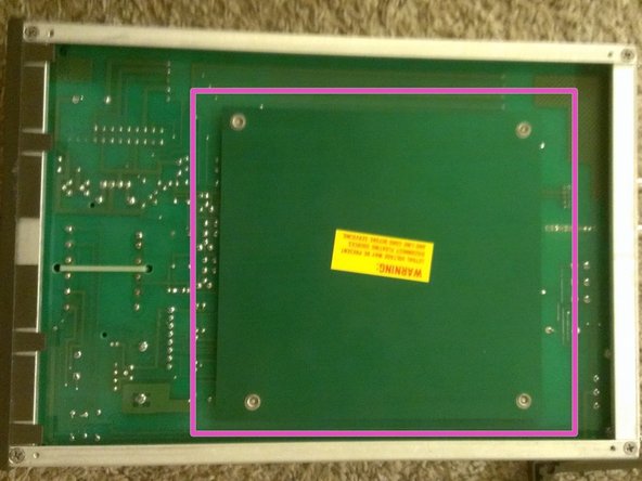
The large metal thing in the center is the upper RFI/EMI shield. It, just like the one on the bottom, protects the sensitive circuits from outside radiation.
-
At this point that should lift right off exposing the circuit board below.
-
At the time you can remove the other side panel just as was done the first. By removing the four screws.
-
-
-
Let's take a quick break from disassembly to investigate the circuit board.
-
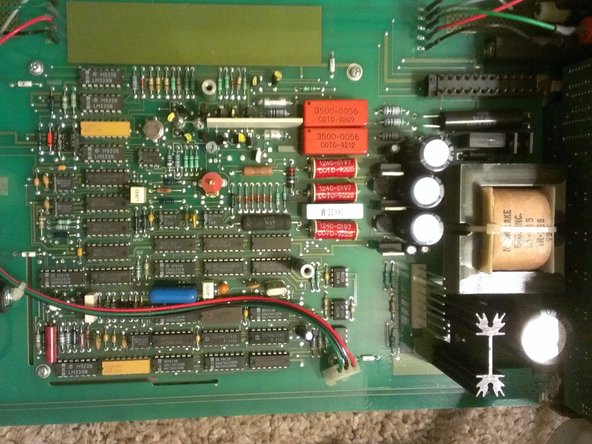
The yellow box is the power supply circuitry. It provides the three regulated and one unregulated rail used by the device.
-
The red box shows the high speed high voltage relays. These switch between ranges. They make a nice soft ping when they activate.
-
The orange section is the multiplexer, most function switching occurs here. The large white square is a high voltage precision matched resistor divider from Craddock
-
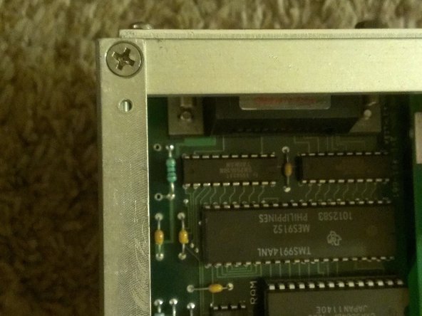
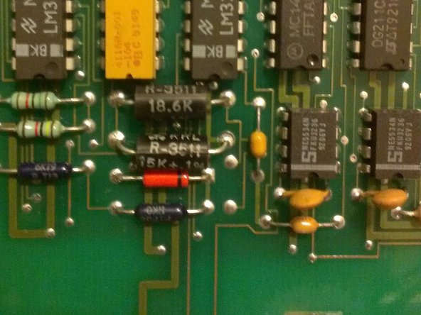
The blue and green boxes hold the -4.2V and -6.4V references respectively. The 6.4V zener (1N4579, shown in image 2) is small, orange and VERY expensive
-
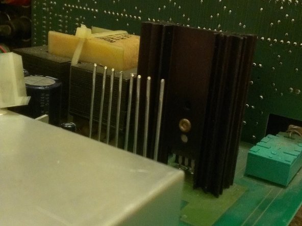
The purple box shows the multi-slope integrator circuit. The white box is the integrating capacitor
-
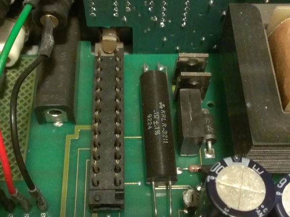
Lastly, the black cylinder with four wires going to it is a special four-wire resistor used in precision current measurements.
-
-
-
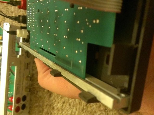
With both sides detaced, the front panel comes off very easily.
-
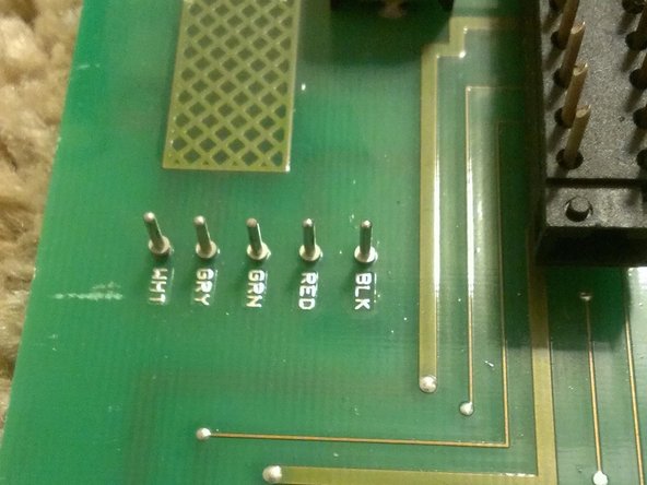
To remove the front panel detach these five wires (which have their color conveniently labeled on the PCB). They are simple pin connectors.
-
To detach the circuit board from the drim. Just remove it from the connectors shown in the third image.
-