はじめに
This teardown can not be used for the OG Xbox Duke.
Individual tools have been listed for teardown of the Hyperkin Duke however the Pro Tech Toolkit or the Essential Electronics Toolkit have all the tools required.
必要な工具と部品
-
-
It would be preferable to conduct this teardown on an anti-static surface or attach an anti-static wrist strap
-
Place controller face down to give access to rear mounted screws
-
Using your #1 Phillips screwdriver remove the seven screws highlight by red marker
-
The controller should easily separate into its two halves, some assistance can be provided by inserting a spudger along the seam
-
-
-
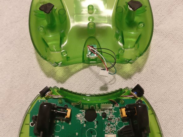
Do not simply pull the rear case off, this is due to the micro USB connector being secured to the rear half of the controller with a cable connecting to the PCB on the front half of the controller
-
Open the controller like a clam shell along the highlighted yellow axis
-
-
-
The angled tweezers are a great tool for removing cables from these connectors
-
Gently wiggle the cable from side to side whilst pulling away from the PCB to separate the two items
-
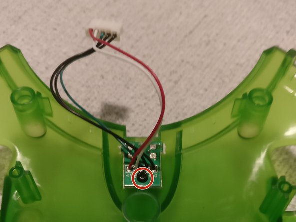
A single screw retains the USB connector PCB to the rear shell of the controller
-
-
-
The center piece, along with the left and right bumpers have been removed simply by sliding them up and away from the controller
-
A similar style of cable/connector as the micro USB is used for the vibration motors
-
Use the angled tweezers in the same manner as before to separate these cables from the PCB connectors
-
Vibration motors can now be lifted out
-
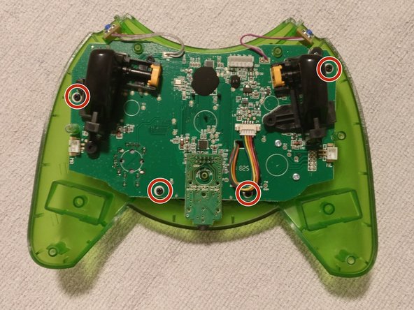
Remove the four screws holding the PCB to the front half of the controller
-
-
-
-
The left and right bumper button PCBs can be slid outwards from their holders and placed out of the way as illustrated
-
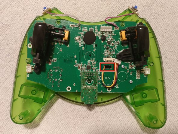
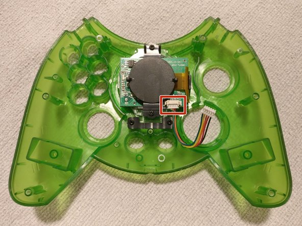
The connector towards the middle of the main PCB is for the LCD. Detach the cable from this connector.
-
Gently lift the main PCB away from the front half of the controller shell.
-
The LCD cable needs to pass through the rectangular hole in the PCB so that the PCB can be completely freed from the controller shell
-
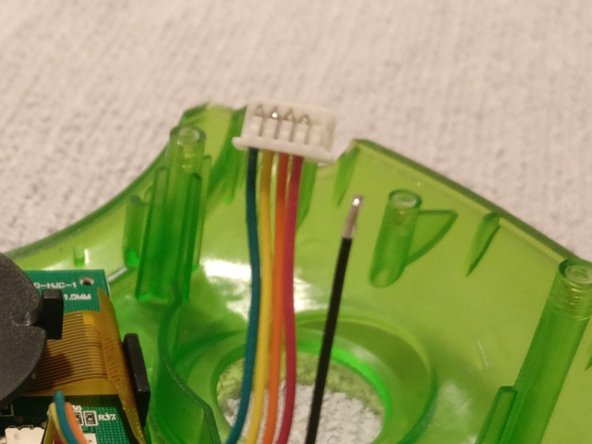
As seen in the picture, one of the small wires came free from the LCD connector. Taking a closer look at the pictures, the cable was never secured correctly from production, if you have issues with your Duke LCD, this might be a good place to start fault finding.
-
If this occurs to you, take note of how the other wires are installed into the connector and slide your loose wire back into the connector the same as the other wires. A click/snap should be felt once the wire has been securely placed back into the connector.
-
-
-
The highlighted buttons can be slid out and removed
-
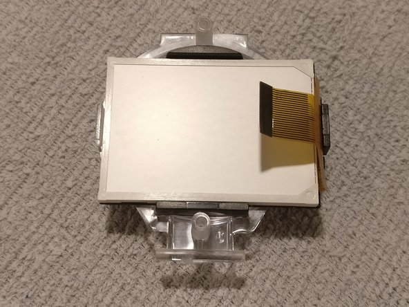
Detach the other end of the LCD cable from the LCD PCB connector
-
A small bracket with two screw retains the LCD to the front half of the controller.
-
Remove the two screws and bracket
-
-
-
The ribbon cable connector has a small relief cutout (red highlighted) this allows for a corner of the opening tool to be inserted
-
Lift in the direction of the arrows to release the ribbon cable from the connector
-
-
-
Hold the thumb stick assembly that is attached to the PCB and pull thumb stick away from assembly
-
-
-
Remove the two screws securing the assembly to the PCB riser
-
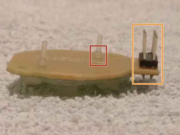
The D-Pad assembly makes electrical connectivity to the main PCB via the orange highlighted connector. To remove, pull D-Pad assembly away from main PCB
-
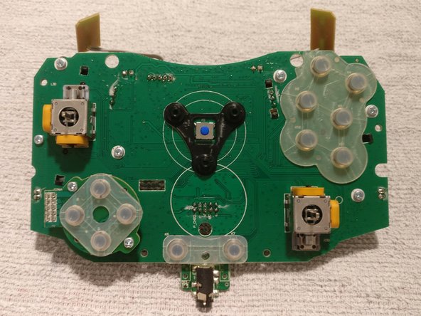
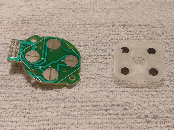
The conductive rubber has been press fitted to the PCB
-
To remove, very gently, as close as possible to the protruding rubber nipple, pull the conductive rubber piece away from the PCB
-
-
-
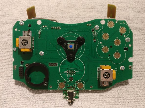
The main PCB conductive pieces can also be removed.
-
To remove, very gently, as close as possible to the protruding rubber nipple, pull the conductive rubber piece away from the PCB
-
During re-assembly, poke rubber nipple through corresponding PCB hole and gently tease rubber nipple though PCB hole with the tweezers.
-