必要な工具と部品
-
-
Holder itself is rather heavy, very stable, made out of coloured thick metal. Big button on the back will release the insert, that holds cleaning sponge.
-
Also, detailed shot of the holding part itself, there are five silicone features that allow to precisely clean the soldering tip. Silicone can withstand high temperatures.
-
-
-
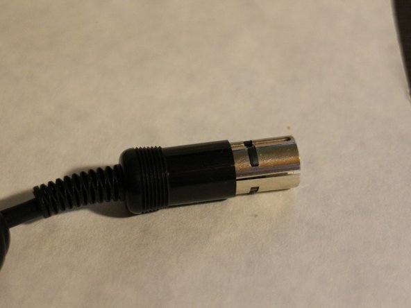
Handle itself, ending with aviation 5-tip connector. There is no screwing mechanism and the connector will wobble inside it´s socket.
-
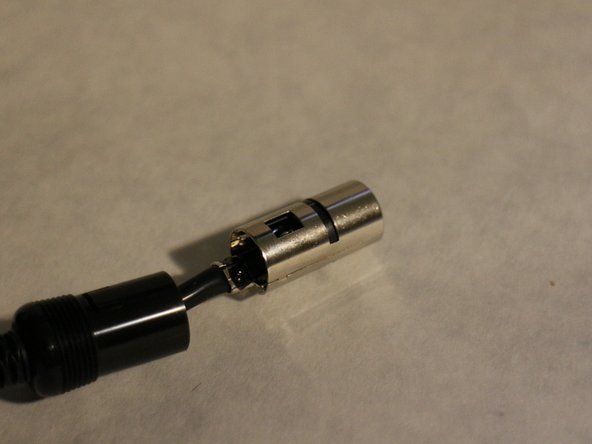
It can be easily disassembled, allowing to look inside and see how are the cables connected.
-
-
-
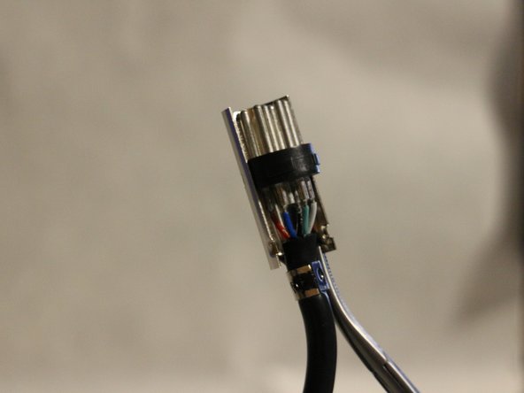
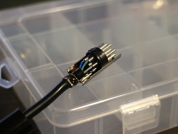
Inside the connector are 5 distinct coloured cables.
-
Counterclockwise, with green on the bottom: Black, grey, green(ground), blue, red.
-
-
-
-
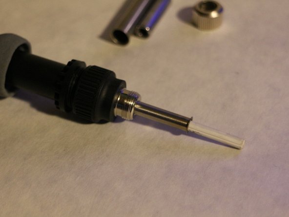
Unscrewing and removing the tip holder, tip itself will easily slide down and reveal the ceramic heating element underneath it.
-
-
-
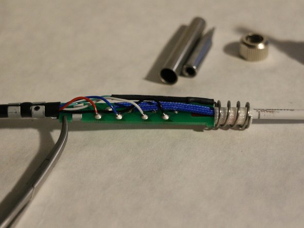
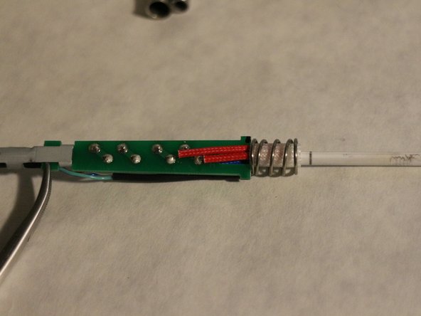
Unscrewing the second part, PCB that holds the ceraming heating elements can be carefully pulled out. It connect the 26V power, temperature sensor and also Ground, which connect to the outer tip via metal spring, grounding the tip and making it ESD safe.
-
Ground cable also has heatshrink, to avoid even potential touching with other, live cables.
-
-
-
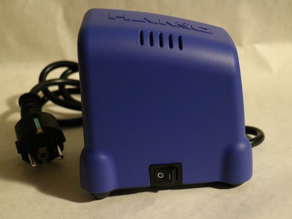
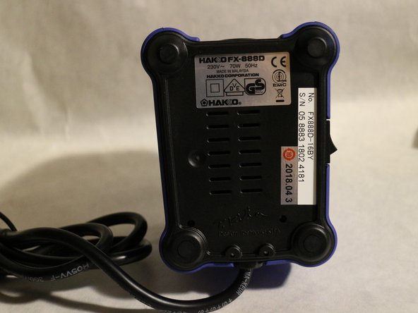
Station is rather heavy, most of it´s weight is due to multi-voltage transformer hiding inside. Outer plastic shell is made from hardened, high-quality PC+ABS mixture.
-
Bottom feet are covered with four rubber discs.
-
-
-
Once the feet are removed, four PH1 screws will be revealed, easily screwed out.
-
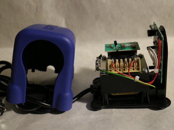
After removing the screws, the top blue plastic shell can be lifted up to reveal the insides.
-
Most of the inside is filled with three components: Transformer, switch and main PCB.
-
-
-
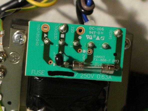
Transformer has a small PCB attached to it, dedicated to fuse mechanism.
-
From the looks of it, transformer is designed for several voltages, including USA voltage, UK voltage and Japan voltage. it´s therefore possible to modify it to fit different voltage.
-
-
-
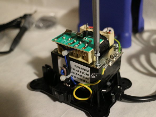
Main PCB is held down by 3 PH2 screws, we´ll remove those.
-
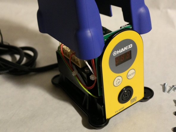
Front of the PCB has a 3-digit display and two switchy buttons. It´s powered with 26V AC voltage, meaning the PCB has to convert it to DC voltages useable by ICs and display.
-
PCB itself is not exactly clean, yet no corrosion is visible. Most of the dirt is uncleaned soldering flux from the factory.
-
The other side has most of the components, there are three prominent ICs and a large MOSFET.
-
IC1: 358,633
-
IC2: RSF100FCA, 1652KN400, Japan ( MCU 16-bit RL78 CISC 4KB Flash 24-Pin HWQFN EP, made by Renesas Electronics )
-
IC3: 9C733
-
Mosfet: GTAO6-600c GK00D VU, CHN, 742
-
-
-
Main switch that turns the station on and off, switches the mains voltage going to the transformer. Live wire (brown one) is the one being switched.
-
-
-
Interesting feature on the connector is, that ground is connected to two different pins, other pin is bridged with a small resistor. Strangely enough, only one pin is connected on the other male connector, leading to a strange redundancy.
-
Color coding on the cable goes as follow:
-
Cable 1: Red
-
Pin 2: Blue
-
Pin 3: Green (ground)
-
Pin 4: White
-
Pin 5: Black
-
Pin 6: Not connected
-


8 件のコメント
Nice photos and description. Maybe check the stand again. I’m pretty sure the stand is ceramic and not metal.
Thanks for your reply. The stand is metal, as it reacts to magnet. I also scratched it a little and metal was revealed underneath it.
Nice write up. I also note that base does respond to magnet.
If I am getting a S-E error with a iron that i know works (I tested it with another base station and works beautifully) but a small flick to the wire plug triggers the S-E error or the 999 error. I thought that it was a connection at the plug but the soldering iron works with other base stations. So assuming its not the iron/wire/plug, what is the base station could cause the S-E error? is it the male plug side? anything else? any ideas?