はじめに
Let's have a look inside a retro Commodore 64 joystick.
必要な工具と部品
-
-
Introduced in 1984, the Commodore 1341 joystick was designed for use with the Commodore range of computers including the Commodore 64, 128, VIC20 and Commodore Plus4.
-
This joystick connects to the retro computers using a 9 pin connection.
-
-
-
-
The joystick is held together by five phillips head screws. One screw is located on the handle and the remaining four are under the base.
-
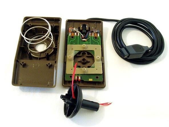
Once the screws have been removed you can pry the case apart using a flat head screw driver. Just be careful with the base as it is spring loaded and it can fly apart quite easily.
-
-
-
You will need to desolder the fire button cables from the board.
-
Pry the case open but watch for the spring. There is also a rubber bung that sits beneath the black rocker shaft.
-
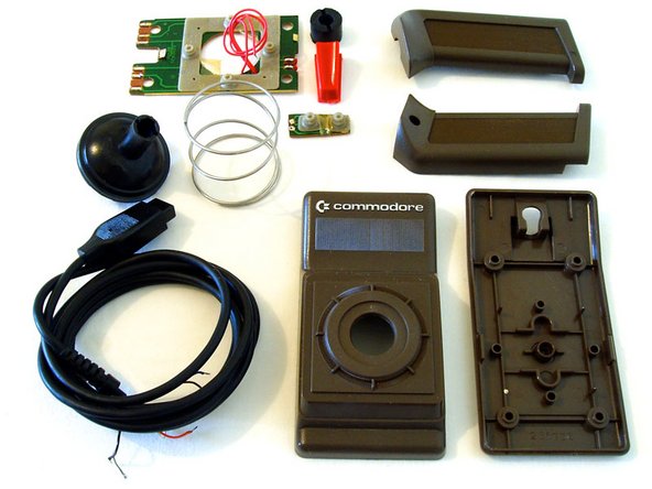
Desolder the cables from the main joystick board and remove all of the components.
-
Now you are ready to clean all of the joystick components and reassemble.
-