必要な工具と部品
-
-
Unlock the button without spring
-
Slide the battery up while unlocking the button with spring
-
-
-
Unscrew the two large screws circled in red
-
Unscrew the two small screws circled in green
-
Slide the plate down and lift the
-
-
-
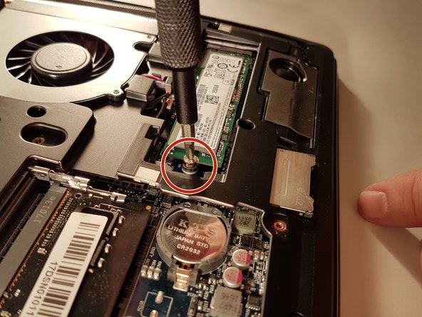
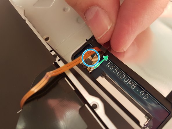
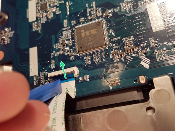
Unscrew the screw circled in red
-
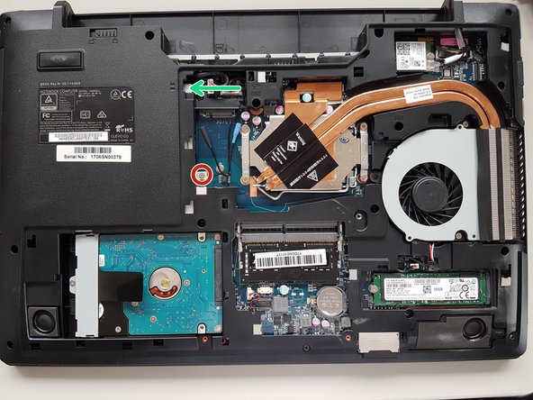
Push the drive to the location indicated by the green arrow
-
Remove the drive from its location
-
-
-
-
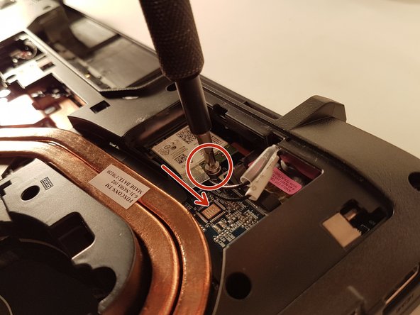
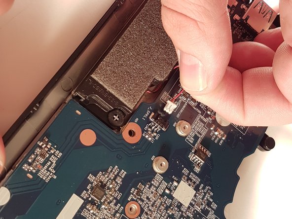
Unscrew the screw circled in red
-
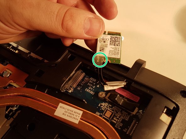
Disconnect the WLAN card in the direction of the red arrow
-
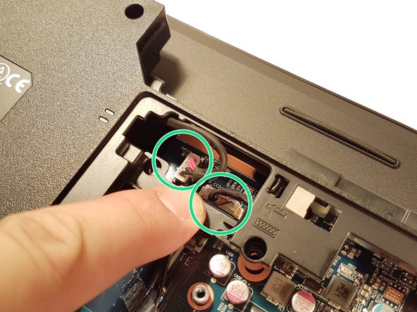
Unhook the two connectors circled in green on the WLAN card
-
-
-
Unscrew the two screws circled in red
-
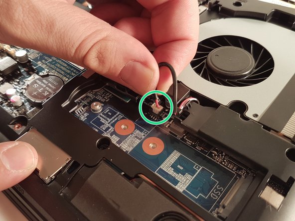
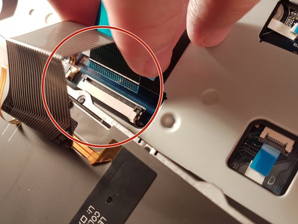
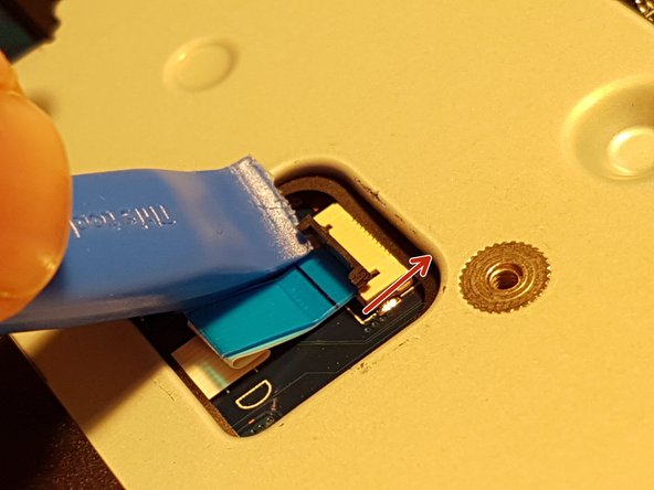
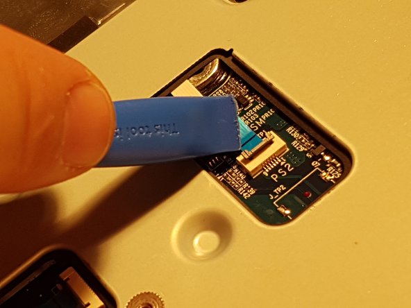
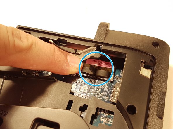
Disconnect the connector surrounded in green
-
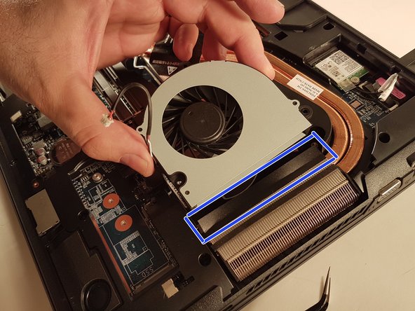
Remove the fan by lifting the blue framed tab
-
-
-
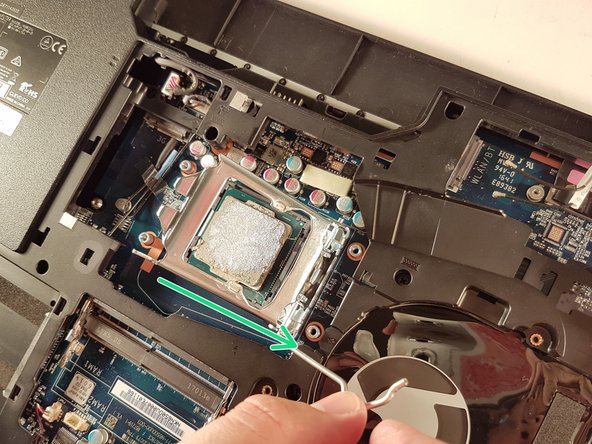
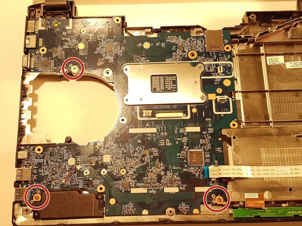
Unscrew the circled screws in red and green
-
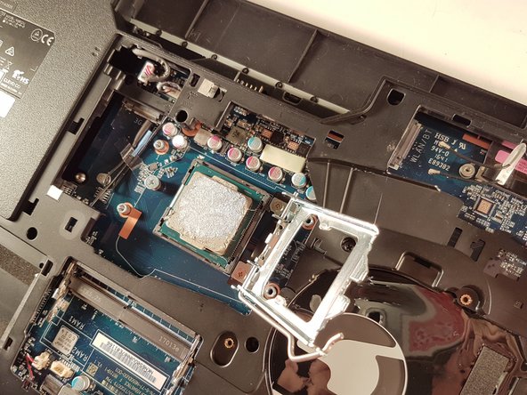
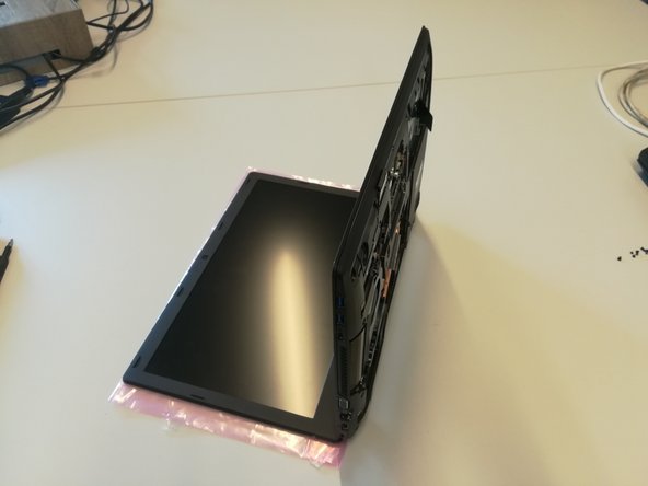
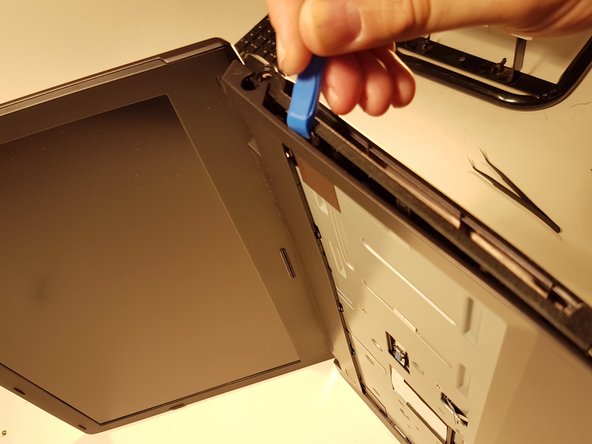
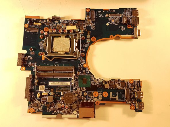
Put the computer in the position of the second image while pushing a paper clip into the hole of the screw circled in green until you hear a click
-
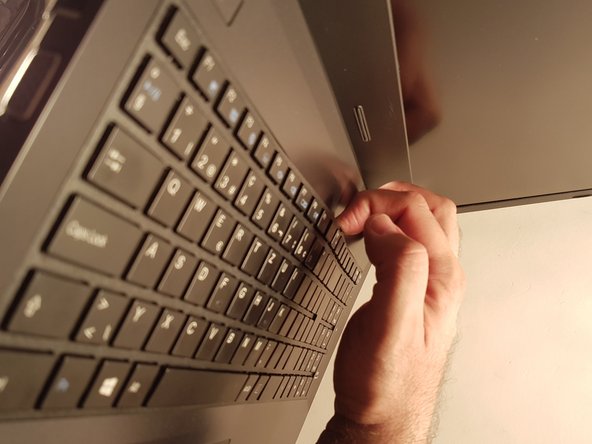
Lift the keyboard
-


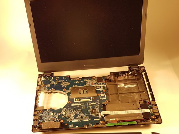


To reassemble your device, follow the instructions in reverse order.
To reassemble your device, follow the instructions in reverse order.
