メインコンテンツにスキップ

why! N131WU/BU/ZU Upper Case Replacement

必要な工具と部品

  1. why! N131WU/BU/ZU Upper Case Replacement, Remove the Screws: 手順 1、 1の画像 1
    • Remove the case screws (red) and the keyboard screws (green).

    • Be sure not to lose these screws. You will need them to reassemble your laptop.

  2. why! N131WU/BU/ZU Upper Case Replacement, Remove the Keyboard: 手順 2、 3の画像 1 why! N131WU/BU/ZU Upper Case Replacement, Remove the Keyboard: 手順 2、 3の画像 2 why! N131WU/BU/ZU Upper Case Replacement, Remove the Keyboard: 手順 2、 3の画像 3
    • Using the hole provided under the case (see picture), push the keyboard out using a thin screwdriver or some other solid object.

    • Hold onto the keyboard as you push the keyboard so as not to damage the two cables still attached.

  3. why! N131WU/BU/ZU Upper Case Replacement, Remove Keyboard Connections: 手順 3、 3の画像 1 why! N131WU/BU/ZU Upper Case Replacement, Remove Keyboard Connections: 手順 3、 3の画像 2 why! N131WU/BU/ZU Upper Case Replacement, Remove Keyboard Connections: 手順 3、 3の画像 3
    • (Blue Cable) Push up on the thin black portion on the connector and gently pull out the blue ribbon cable until it comes out.

    • (Orange Cable) Remove the orange cable by sliding the gray part of the connector towards the screen, then gently pull on the ribbon cable.

  4. why! N131WU/BU/ZU Upper Case Replacement, Remove the upper screws: 手順 4、 2の画像 1 why! N131WU/BU/ZU Upper Case Replacement, Remove the upper screws: 手順 4、 2の画像 2
    • Unscrew the three screws that were under the keyboard. Be sure to hold onto these.

    • After these are removed, you can now remove the lower part of the case from the rest of the computer.

  5. why! N131WU/BU/ZU Upper Case Replacement, Remove the SSD: 手順 5、 3の画像 1 why! N131WU/BU/ZU Upper Case Replacement, Remove the SSD: 手順 5、 3の画像 2 why! N131WU/BU/ZU Upper Case Replacement, Remove the SSD: 手順 5、 3の画像 3
    • Remove the screw holding in the ssd.

    • Carefully remove the SSD from the connector.

  6. why! N131WU/BU/ZU Upper Case Replacement, RAM (Memory): 手順 6、 3の画像 1 why! N131WU/BU/ZU Upper Case Replacement, RAM (Memory): 手順 6、 3の画像 2 why! N131WU/BU/ZU Upper Case Replacement, RAM (Memory): 手順 6、 3の画像 3
    • Gently pull outwards on the clips to free the RAM stick.

    • Remove the RAM Stick from its slot.

  7. why! N131WU/BU/ZU Upper Case Replacement, Battery: 手順 7、 2の画像 1 why! N131WU/BU/ZU Upper Case Replacement, Battery: 手順 7、 2の画像 2
    • Remove the five Phillips screws securing the battery.

    • Unplug the power connector and lift the battery out in the direction of the arrows to remove it.

  8. why! N131WU/BU/ZU Upper Case Replacement, Motherboard: 手順 8、 3の画像 1 why! N131WU/BU/ZU Upper Case Replacement, Motherboard: 手順 8、 3の画像 2 why! N131WU/BU/ZU Upper Case Replacement, Motherboard: 手順 8、 3の画像 3
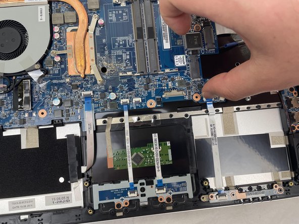
    • Lift the retaining latch and unplug the ZIF cable found under the keyboard.

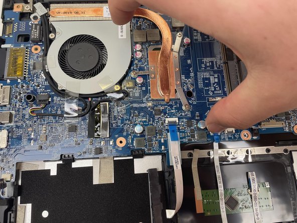
    • Disconnect the nine marked cables as detailed in the following steps.

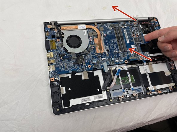
    • Remove the four screws securing the motherboard to the case.

  9. why! N131WU/BU/ZU Upper Case Replacement, ZIF Connectors: 手順 9、 3の画像 1 why! N131WU/BU/ZU Upper Case Replacement, ZIF Connectors: 手順 9、 3の画像 2 why! N131WU/BU/ZU Upper Case Replacement, ZIF Connectors: 手順 9、 3の画像 3
    • The cables with the blue reinforcing tabs are ZIF connectors that require you to lift the retaining lever before removing the cable.

  10. why! N131WU/BU/ZU Upper Case Replacement, SATA Cable: 手順 10、 3の画像 1 why! N131WU/BU/ZU Upper Case Replacement, SATA Cable: 手順 10、 3の画像 2 why! N131WU/BU/ZU Upper Case Replacement, SATA Cable: 手順 10、 3の画像 3
    • Remove the SATA3 cable from the motherboard after disconnecting it.

  11. why! N131WU/BU/ZU Upper Case Replacement, Motherboard (continued): 手順 11、 2の画像 1 why! N131WU/BU/ZU Upper Case Replacement, Motherboard (continued): 手順 11、 2の画像 2
    • Don't forget to remove these cables.

  12. why! N131WU/BU/ZU Upper Case Replacement, Display Connector: 手順 12、 2の画像 1 why! N131WU/BU/ZU Upper Case Replacement, Display Connector: 手順 12、 2の画像 2
    • Note: The original instructions call for inserting your thumbnail firmly under the base of the display connector

    • However, the proper way to remove the display connector is to grasp the plastic strap on top of the connector and use it to pull the connector straight up.

  13. why! N131WU/BU/ZU Upper Case Replacement, Remove the Motherboard: 手順 13、 3の画像 1 why! N131WU/BU/ZU Upper Case Replacement, Remove the Motherboard: 手順 13、 3の画像 2 why! N131WU/BU/ZU Upper Case Replacement, Remove the Motherboard: 手順 13、 3の画像 3
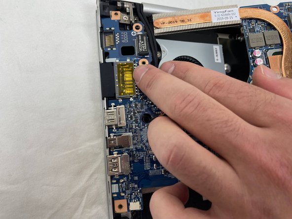
    • Once the screws have been removed, carefully lift the motherboard from the end indicated by the arrows.

    • Remember to disconnect the cables near the fan.

  14. why! N131WU/BU/ZU Upper Case Replacement, Motherboard (continued): 手順 14、 1の画像 1
    • The motherboard has been successfully removed.

  15. why! N131WU/BU/ZU Upper Case Replacement, Speakers: 手順 15、 3の画像 1 why! N131WU/BU/ZU Upper Case Replacement, Speakers: 手順 15、 3の画像 2 why! N131WU/BU/ZU Upper Case Replacement, Speakers: 手順 15、 3の画像 3
    • Remove the right speaker.

    • To remove the left speaker, first peel off the microphone/headset cable, then the adhesive strips.

  16. why! N131WU/BU/ZU Upper Case Replacement, Speaker/Fan/Headset connector: 手順 16、 3の画像 1 why! N131WU/BU/ZU Upper Case Replacement, Speaker/Fan/Headset connector: 手順 16、 3の画像 2 why! N131WU/BU/ZU Upper Case Replacement, Speaker/Fan/Headset connector: 手順 16、 3の画像 3
    • Remove the left speaker.

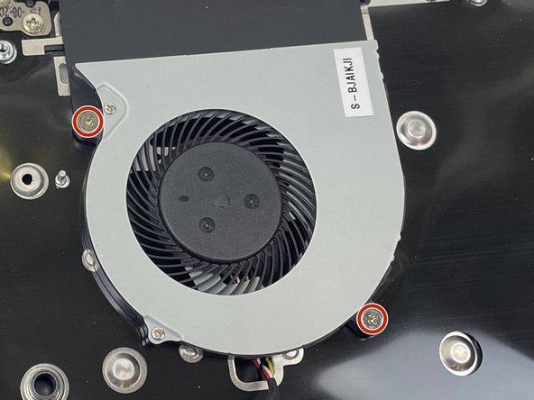
    • Remove the two Phillips screws securing the CPU fan to the case and remove the fan.

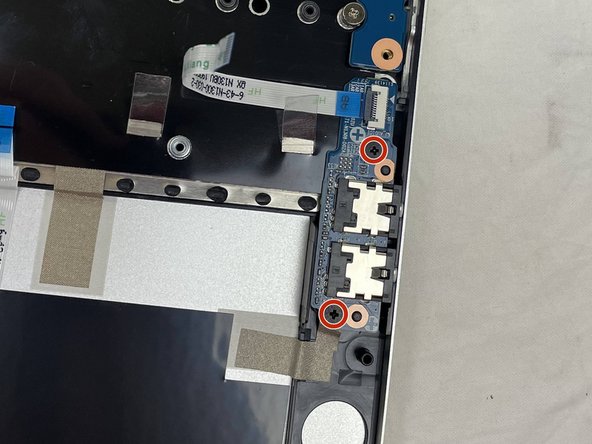
    • Remove the two screws securing the audio connector board.

  17. why! N131WU/BU/ZU Upper Case Replacement, Headset and USB Boards: 手順 17、 3の画像 1 why! N131WU/BU/ZU Upper Case Replacement, Headset and USB Boards: 手順 17、 3の画像 2 why! N131WU/BU/ZU Upper Case Replacement, Headset and USB Boards: 手順 17、 3の画像 3
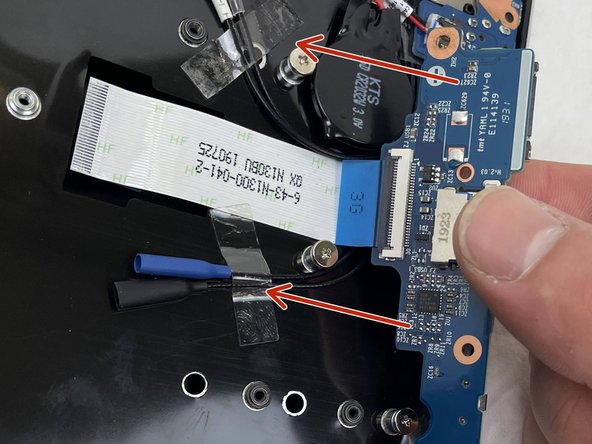
    • Lift the audio board at the point indicated by the red arrow and slide it away from the chassis in the direction of the orange arrow.

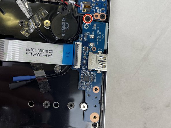
    • Remove the Phillips screw securing the power connector board.

    • Lift out the USB connector board in the direction indicated by the arrows.

    • The ribbon cable is secured to the upper case with adhesive. It is not necessary to disconnect it from the USB board; just carefully peel the entire assembly from the case in the direction of the arrows.

  18. why! N131WU/BU/ZU Upper Case Replacement, DC Board and CMOS Battery: 手順 18、 3の画像 1 why! N131WU/BU/ZU Upper Case Replacement, DC Board and CMOS Battery: 手順 18、 3の画像 2 why! N131WU/BU/ZU Upper Case Replacement, DC Board and CMOS Battery: 手順 18、 3の画像 3
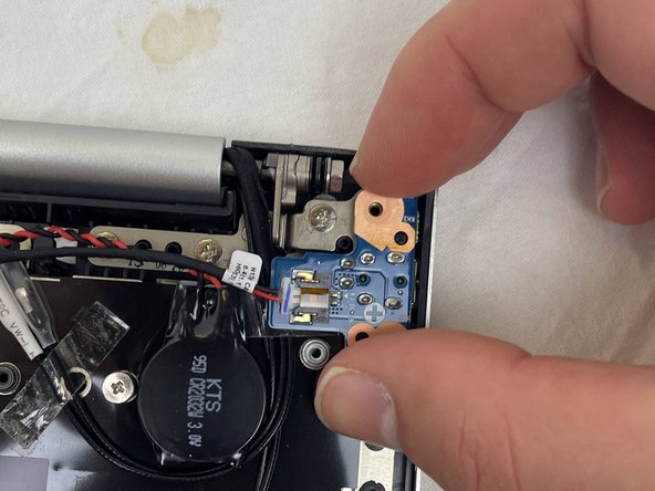
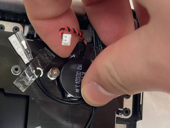
    • Unplug the DC input board, remove the single Phillips screw securing it and remove it.

    • The DC power wires can remain in place.

    • The CMOS battery is secured to the case with adhesive. Simply peel it off to remove it.

  19. why! N131WU/BU/ZU Upper Case Replacement, LED Board / Touchpad Button Plate: 手順 19、 3の画像 1 why! N131WU/BU/ZU Upper Case Replacement, LED Board / Touchpad Button Plate: 手順 19、 3の画像 2 why! N131WU/BU/ZU Upper Case Replacement, LED Board / Touchpad Button Plate: 手順 19、 3の画像 3
    • Remove the two screws holding the LED board on the chassis and remove it along with the ribbon cable.

    • No force is necessary; it is lightly adhered to the board and can easily be peeled off.

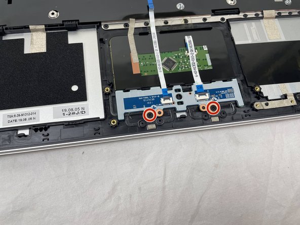
    • Remove the two screws securing the touchpad button plate.

  20. why! N131WU/BU/ZU Upper Case Replacement, Touchpad Button Board: 手順 20、 3の画像 1 why! N131WU/BU/ZU Upper Case Replacement, Touchpad Button Board: 手順 20、 3の画像 2 why! N131WU/BU/ZU Upper Case Replacement, Touchpad Button Board: 手順 20、 3の画像 3
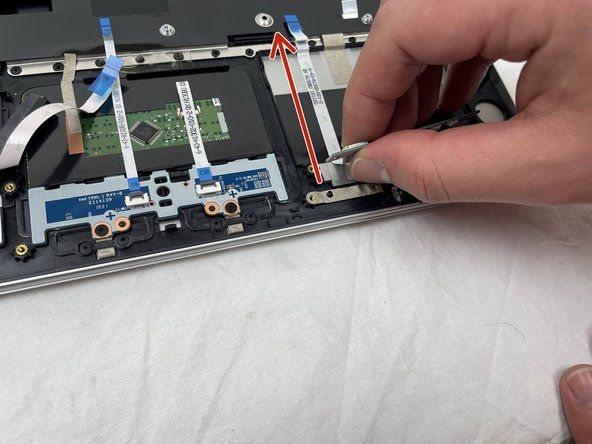
    • Lift the ZIF connector retaining tab and unplug the button cable on the right.

    • Grasp the LED board between the two cables.

    • Following the direction of the red arrow, peel the two cables from the case.

  21. why! N131WU/BU/ZU Upper Case Replacement, Cable Tapes / Hinge Screws: 手順 21、 3の画像 1 why! N131WU/BU/ZU Upper Case Replacement, Cable Tapes / Hinge Screws: 手順 21、 3の画像 2 why! N131WU/BU/ZU Upper Case Replacement, Cable Tapes / Hinge Screws: 手順 21、 3の画像 3
    • Peel off the pieces of tape holding the cables onto the chassis.

    • Remove the six Phillips screws securing the hinges, three on each side.

  22. why! N131WU/BU/ZU Upper Case Replacement, Upper Case: 手順 22、 3の画像 1 why! N131WU/BU/ZU Upper Case Replacement, Upper Case: 手順 22、 3の画像 2 why! N131WU/BU/ZU Upper Case Replacement, Upper Case: 手順 22、 3の画像 3
    • While holding down the display, lift the chassis up to about a 45 degree angle.

    • The case will slide out once there is sufficient clearance.

終わりに

To reassemble your device, follow these instructions in reverse order.

ある他の人がこのガイドを完成しました。

以下の翻訳者の皆さんにお礼を申し上げます:

fr en

100%

これらの翻訳者の方々は世界を修理する私たちのサポートをしてくれています。 あなたも貢献してみませんか?
翻訳を始める ›

作成者

1人の作成者と共同作成されました。

Felice Suglia

メンバー登録日: 06/15/13

31,100 ポイント

264のガイドは作成済み

0 件のコメント

コメントを追加

統計データ:

過去 24時間: 1

過去 7 日: 6

過去 30 日: 22

今までの合計 173