メインコンテンツにスキップ

このバージョンは誤った内容を含んでいる可能性があります。最新の承認済みスナップショットに切り替えてください。

必要な工具と部品

  1. この手順は未翻訳です。 翻訳を手伝う。

    : 手順 1、 1の画像 1
    • Flip over the device and remove the two 11.5 mm screws using the Phillips #1 screwdriver.

  2. この手順は未翻訳です。 翻訳を手伝う。

    : 手順 2、 2の画像 1 : 手順 2、 2の画像 2
    • Unscrew the back plate using a Phillips #1 screwdriver.

    • Carefully lift the panel up once the screws are removed.

  3. この手順は未翻訳です。 翻訳を手伝う。

    : 手順 3、 2の画像 1 : 手順 3、 2の画像 2
    • With both hands, grab the two black tabs on each end of the battery.

    • Pull the tabs upwards to remove the battery.

  4. この手順は未翻訳です。 翻訳を手伝う。

    : 手順 4、 2の画像 1 : 手順 4、 2の画像 2
    • Remove the dust bin by pressing down on the rear button on the device.

    • Pull the bin towards you to remove it.

  5. この手順は未翻訳です。 翻訳を手伝う。

    : 手順 5、 2の画像 1 : 手順 5、 2の画像 2
    • Insert the opening tool in the back of the device under the wedge.

    • Slowly pry the plate loose and lift it from the device.

    • The face plate is only designed to be removed back to front.

  6. この手順は未翻訳です。 翻訳を手伝う。

    : 手順 6、 2の画像 1 : 手順 6、 2の画像 2
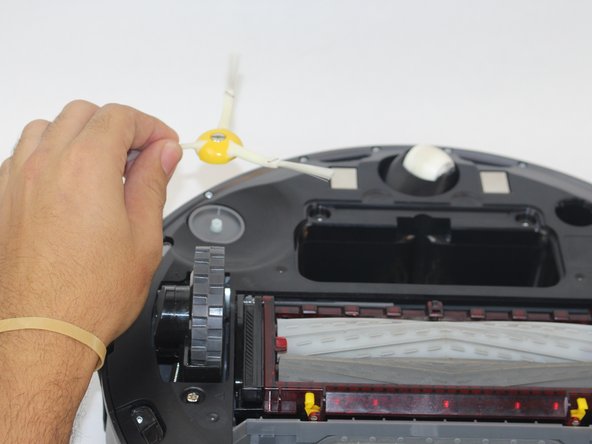
    • Loosen the screw holding the side brush in place, by using a Phillips #1 screwdriver

    • The screw is attached to the side brush and does not come out completely.

    • Lift the side brush.

  7. この手順は未翻訳です。 翻訳を手伝う。

    : 手順 7、 2の画像 1 : 手順 7、 2の画像 2
    • Remove the two 11.5mm screws holding down the bottom plate using a Phillips #1 screwdriver

    • Carefully lift the bottom plate.

  8. この手順は未翻訳です。 翻訳を手伝う。

    : 手順 8、 3の画像 1 : 手順 8、 3の画像 2 : 手順 8、 3の画像 3
    • Remove the four 15.8mm gold screws around the brush module using the Phillips #1 screwdriver.

    • Lift the brush module carefully using both hands.

  9. この手順は未翻訳です。 翻訳を手伝う。

    : 手順 9、 3の画像 1 : 手順 9、 3の画像 2 : 手順 9、 3の画像 3
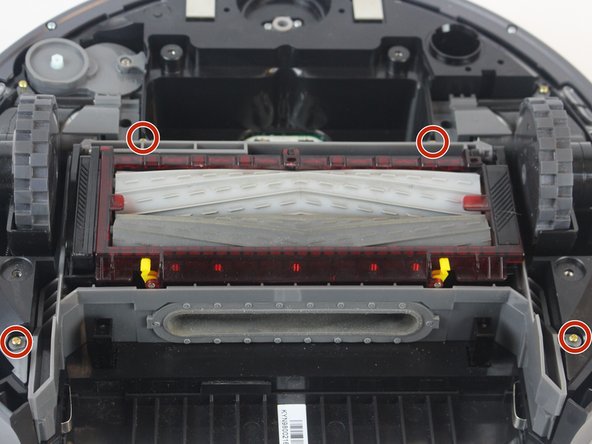
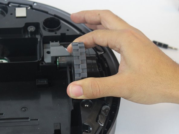
    • Remove the three 15.8mm gold screws with a Phillips #1 screwdriver.

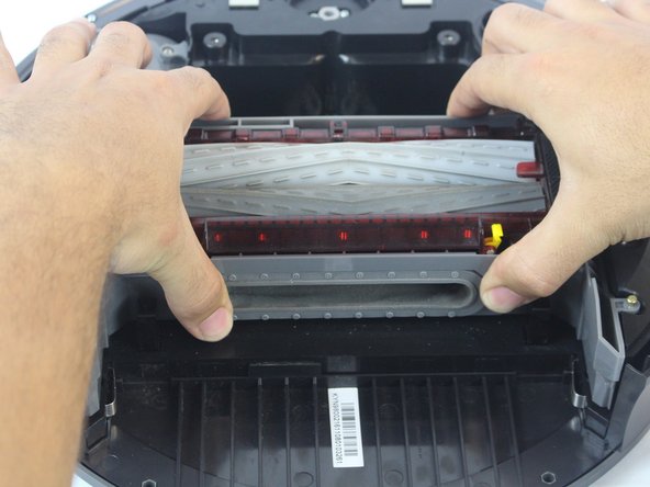
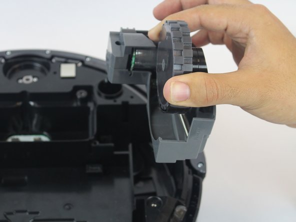
    • Lift the wheel module to remove it from the vacuum.

    • Remove the other wheel by repeating these steps.

  10. この手順は未翻訳です。 翻訳を手伝う。

    : 手順 10、 2の画像 1 : 手順 10、 2の画像 2
    • Remove the ten 6.1 mm silver screws using a Phillips #1 screwdriver.

    • Lift the bottom guard off the front sensor panel by pulling it upwards.

  11. この手順は未翻訳です。 翻訳を手伝う。

    : 手順 11、 2の画像 1 : 手順 11、 2の画像 2
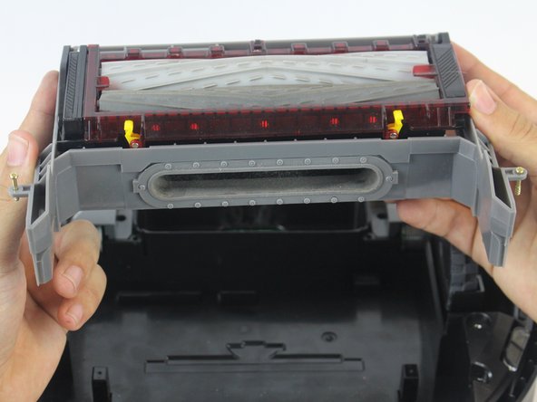
    • Lift the two corner guards at the rear of the device by lifting and popping them out.

    • Pull the front sensor away slowly from the vacuum.

    • The cable connecting the front sensor to the Roomba is delicate, so proceed with caution.

  12. この手順は未翻訳です。 翻訳を手伝う。

    : 手順 12、 1の画像 1
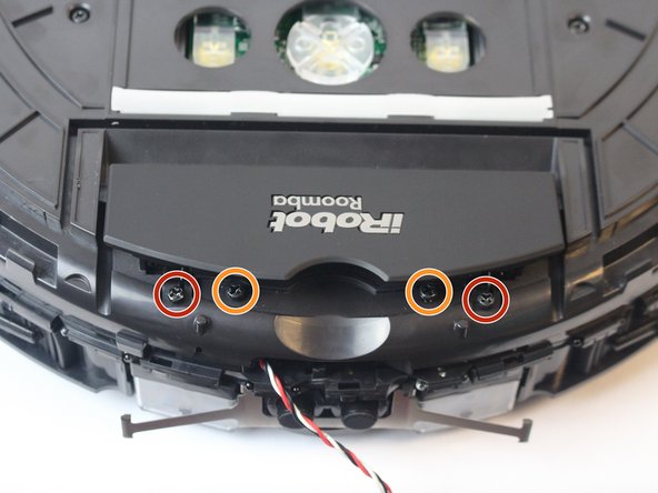
    • Flip the sensor over and use a Phillips #1 screwdriver to remove the two 3.8 mm silver screws that hold the sensors to the panel.

    • While the two 3.8mm screws look very similar to the 6.1mm screws, the two sizes are not interchangeable, so make sure not to mix the two sizes up when reassembling the Roomba.

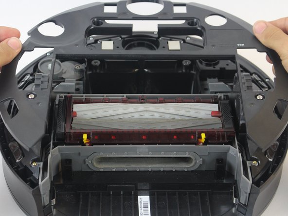
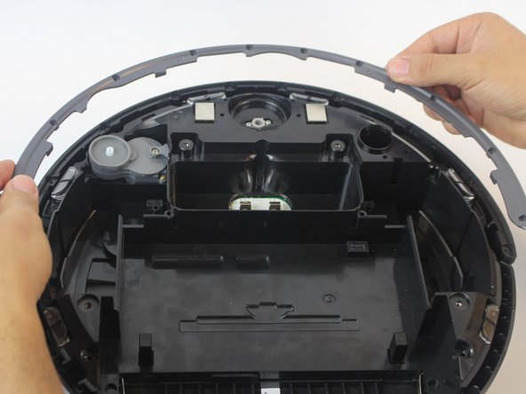
    • Once removed, pull the panel away carefully.

  13. この手順は未翻訳です。 翻訳を手伝う。

    : 手順 13、 2の画像 1 : 手順 13、 2の画像 2
    • Remove the fourteen 6.6 mm black screws holding down the top plate using a Phillips #1 screwdriver.

    • Push the lip back towards the logo to remove two 6.6 mm black screws found under it using a Phillips #1 screwdriver.

  14. この手順は未翻訳です。 翻訳を手伝う。

    : 手順 14、 2の画像 1 : 手順 14、 2の画像 2
    • Lift the top plate slowly, being careful not to damage the vacuum components while exposing the motherboard.

  15. この手順は未翻訳です。 翻訳を手伝う。

    : 手順 15、 2の画像 1 : 手順 15、 2の画像 2
    • Remove the nine 6.4 mm silver screws holding the motherboard to the vacuum body and the clear plastic guard using a Phillips #1 screwdriver.

    • Carefully remove the connector-clips that are attached to the motherboard.

    • Some connectors will be difficult to remove.

  16. この手順は未翻訳です。 翻訳を手伝う。

    : 手順 16、 3の画像 1 : 手順 16、 3の画像 2 : 手順 16、 3の画像 3
    • Using both hands, lift the motherboard connected to the camera away from the device's main motherboard.

    • Only lift the motherboard upwards to avoid bending the pins and causing further damage to the device's electronics.

    • Remove the black plastic guard that is placed in between the two computer boards

  17. この手順は未翻訳です。 翻訳を手伝う。

    : 手順 17、 2の画像 1 : 手順 17、 2の画像 2
    • Lift the main motherboard upward and off of the vacuum.

    • The screw inserts are holding it in place so it will have to be lifted evenly.

    • Remove the motherboard from your device.

ゴール

21 の人々がこのガイドを完成させました。

作成者

7人の作成者と共同で作成されました。

Ernesto Rodriguez Romero

メンバー登録日: 09/27/17

965 ポイント

4のガイドは作成済み

チーム

USF Tampa, Team S14-G2, Boczar Fall 2017 USF Tampa, Team S14-G2, Boczar Fall 2017人のメンバー

USFT-BOCZAR-F17S14G2

4 メンバー

5のガイドは作成済み

9 件のコメント

Thank you for the replacement instructions & pictures…so helpful!

Any idea where I can purchase a roomba 980 motherboard?

LMSterling - 返信

Where can I purchase the roomba 980 motherboard?

Michael Goshorn - 返信

aliexpress my friend

hamilton.gazim -

you don’t need to take out the modules to take out the circuit board

LakeM0nst3r - 返信

If you find a rectangular rubber grommet left over when you’ve finished, it goes in a slot behind the dust bin and you can reinsert it from the outside just by removing the bin first.

James Turner - 返信

コメントを追加

統計データ:

過去 24時間: 12

過去 7 日: 47

過去 30 日: 166

今までの合計 16,732