メインコンテンツにスキップ

iRULU AX106 Logic Board Replacement

必要な工具と部品

  1. iRULU AX106 Logic Board Replacement, iRULU AX106 Disassembly: 手順 1、 1の画像 1
    • Using a Philips head #00 screwdriver locate and remove each of the four screws located along the tall side of the iRulu.

    • There may be plastic covers protecting the screws, if this is the case take a phillips head screwdriver, and gently apply pressure on the covers until they come off.

  2. iRULU AX106 Logic Board Replacement: 手順 2、 2の画像 1 iRULU AX106 Logic Board Replacement: 手順 2、 2の画像 2
    • Use the opening tool to pry the screen from the case applying pressure at each of the four corners of the screen.

    • While a good deal of force is required to separate the screen from the case, make sure to separate the screen from the case at each corner before attempting to completely remove the screen. There are delicate wires that may be damaged if the screen is removed is before the corners are separated.

  3. iRULU AX106 Logic Board Replacement: 手順 3、 3の画像 1 iRULU AX106 Logic Board Replacement: 手順 3、 3の画像 2 iRULU AX106 Logic Board Replacement: 手順 3、 3の画像 3
    • Using a pair of tweezers, gently unplug connectors A and B from the logic board.

    • Completely separate the screen and case.

  4. iRULU AX106 Logic Board Replacement, Logic Board: 手順 4、 2の画像 1 iRULU AX106 Logic Board Replacement, Logic Board: 手順 4、 2の画像 2
    この手順で使用する道具:
    Desoldering Pump
    $3.99
    購入する
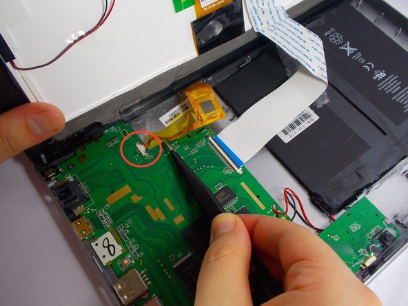
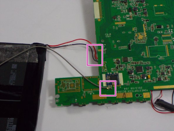
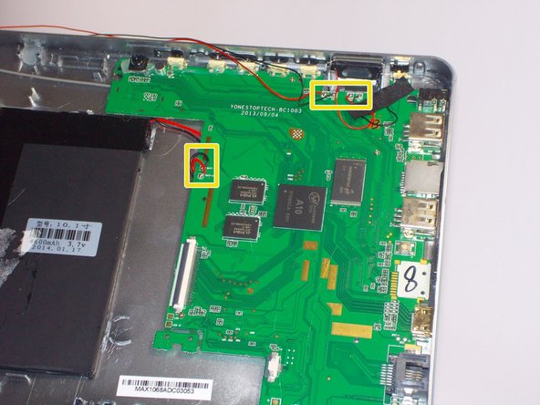
    • Locate where the speaker wires are attached to the logic board, and use a soldering iron and solder sucker to remove the wires from the board.

    • Then, locate the wires connecting the logic board to the battery and desolder them the same way.

    • The soldering iron is extremely hot. Please use caution when using these tools.

  5. iRULU AX106 Logic Board Replacement: 手順 5、 2の画像 1 iRULU AX106 Logic Board Replacement: 手順 5、 2の画像 2
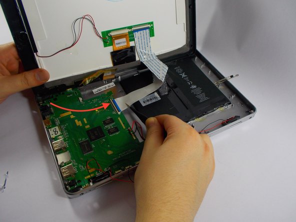
    • Completely remove the old logic board, being careful not to damage any wires

    • Place the new logic board exactly where the old one was located. Leave the wires in an easily accessible position.

    • Solder the wires in the corresponding places exactly where you disconnected them from the old logic board.

終わりに

To reassemble your device, follow these instructions in reverse order.

作成者

3人の作成者と共同で作成されました。

Victoria Holbrook

メンバー登録日: 03/24/15

15 ポイント

1ガイドが承認済み

チーム

UMass Dartmouth, Team 4-7, Vijaybhaskar Spring 2015 UMass Dartmouth, Team 4-7, Vijaybhaskar Spring 2015人のメンバー

UMASSD-VIJAYBHASKAR-S15S4G7

3 メンバー

8のガイドは作成済み

コメント 1 件

very very good¡¡¡¡

jorgemcglez - 返信

コメントを追加

統計データ:

過去 24時間: 0

過去 7 日: 1

過去 30 日: 2

今までの合計 854