この翻訳は、ソースガイドの最新の更新を反映していない可能性があります。 翻訳の更新に協力してください。 または ソースガイドを参照してください。
はじめに
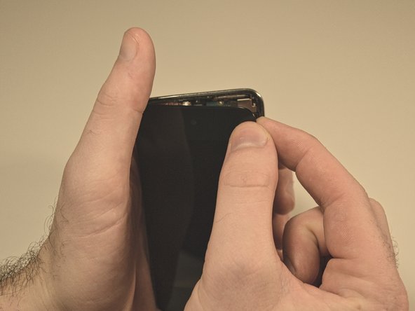
このガイドは、iPod touch 第4世代で30ピンDockコネクタを修理する際に使用してください。
"注意":この作業では、半田付けが必要です。
必要な工具と部品
-
-
この手順は未翻訳です。 翻訳を手伝う。
-
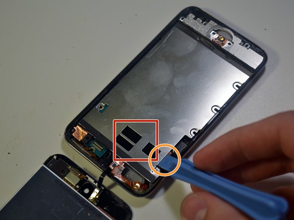
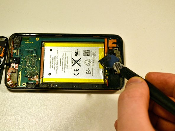
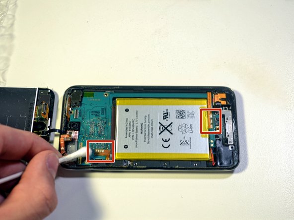
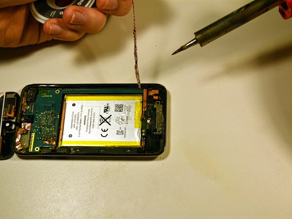
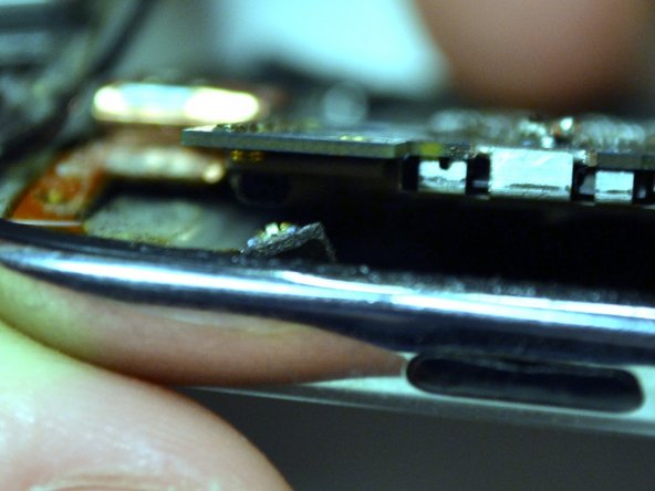
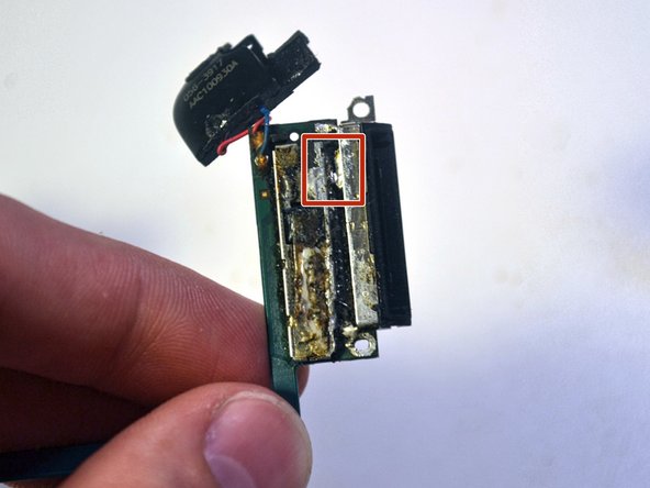
Areas highlighted in red show three solder joints to the right of the battery, along with four smaller solder joints located to the left of the battery.
-
These joints secure the power/volume flex cable (leftmost joint) and the battery flex cable (rightmost joint) to the logic board.
-
In the next few steps you will desolder the battery and power/volume flex cables from the logic board.
-
-
この手順は未翻訳です。 翻訳を手伝う。
-
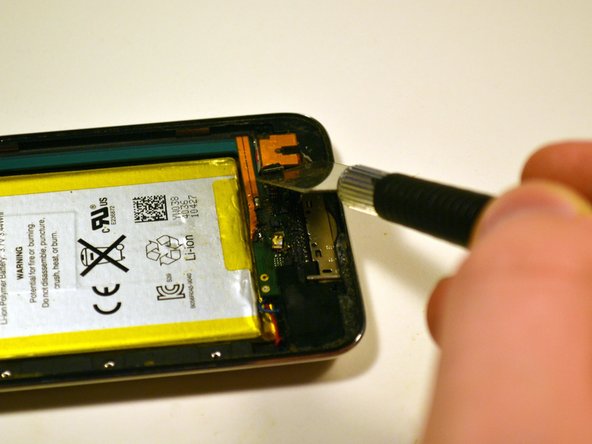
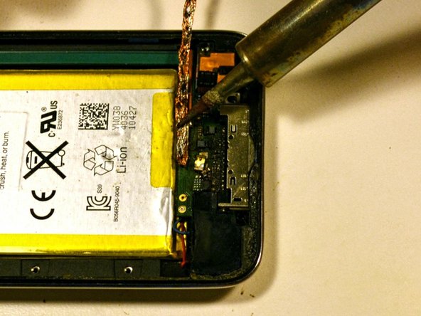
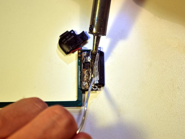
To desolder the battery flex cable, place a copper desoldering braid on top of the existing solder pads and press down on the braid with the soldering iron.
-
Once the solder melts and flows into the braid, remove the braid from the pad.
-
Repeat this process for the power/volume flex cable.
-
-
この手順は未翻訳です。 翻訳を手伝う。
-
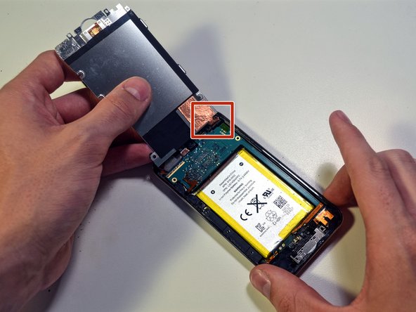
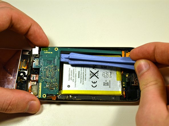
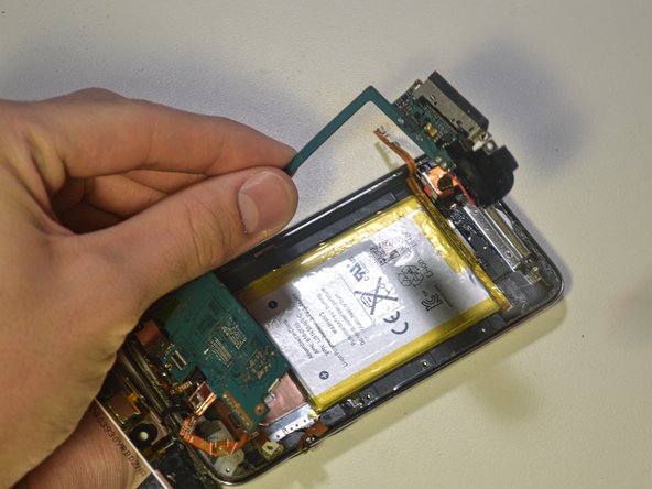
Starting above the battery near the power/volume cable attachment, use a cell phone prying tool to slowly pry the logic board straight up.
-
At this point, the top of the logic board should be lifted from the case. The bottom of the logic board and the wifi cable should still be attached to the steel housing.
-
-
この手順は未翻訳です。 翻訳を手伝う。
-
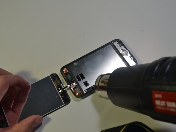
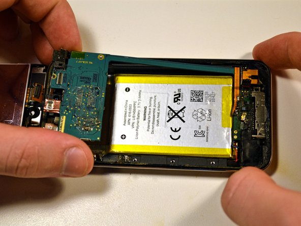
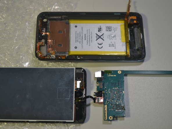
Lightly heat the areas in red with your heat gun to soften the adhesive underneath the logic board.
-
Once heated, gently pry the logic board up with a cell phone opening tool.
-
Lift the bottom of the logic board out of the casing with your fingers.
-
Remove the logic board from the steel casing.
-
-
この手順は未翻訳です。 翻訳を手伝う。
-
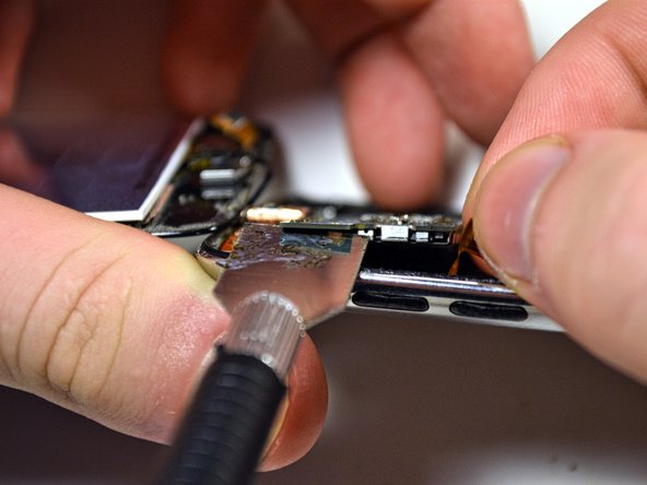
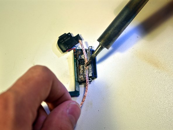
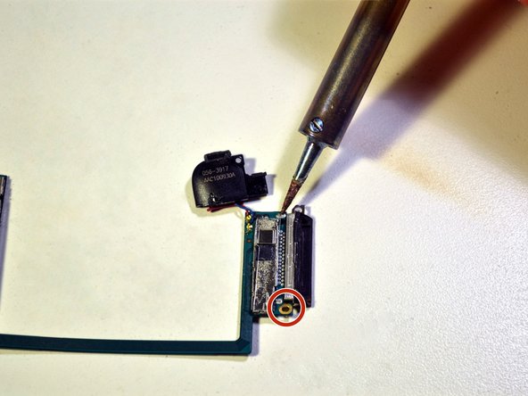
Desolder the two solder joints and the 30 pins.
-
To desolder the solder joint, place a copper desoldering braid on top of the existing solder and press down on the braid with the soldering iron.
-
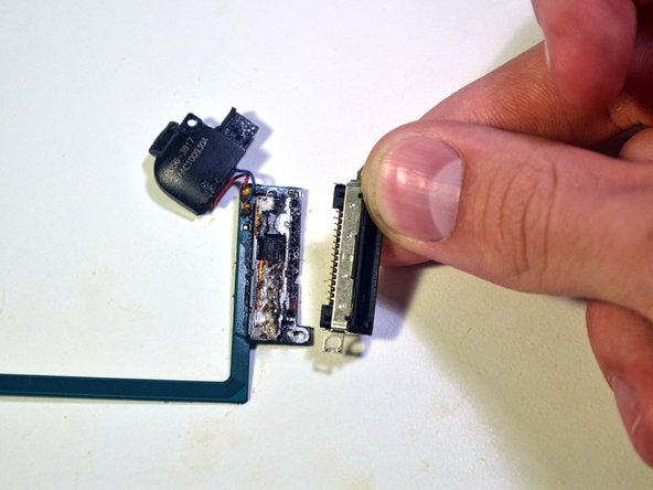
Once the solder melts and flows into the braid, remove the braid from the pad.
-
Repeat this same process for the other solder joint and all 30 pins.
-
-
この手順は未翻訳です。 翻訳を手伝う。
-
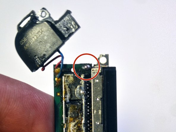
Solder the two metal joints back to the logic board.
-
Place the tip of the soldering iron against the metal joint.
-
Melt solder so that it forms a dome on top of the joint.
-
Remove both the solder and the soldering iron tip from the solder pad as soon as enough solder melts onto the pad.
-
When complete, the soldered pads should have an ovular, pill like shape.
-
-
この手順は未翻訳です。 翻訳を手伝う。
-
Solder all 30 pins back to the logic board.
-
Heat all 30 pins with the tip of the soldering iron.
-
Melt a drop of solder onto the pins and spread it around with the tip of the soldering iron.
-
Repeat until all pins are covered in solder.
-
Remove any excess solder with desoldering braid.
-


修理が完了したら、逆の手順で組み直してください。
修理が完了したら、逆の手順で組み直してください。
9 の人々がこのガイドを完成させました。
以下の翻訳者の皆さんにお礼を申し上げます:
50%

これらの翻訳者の方々は世界を修理する私たちのサポートをしてくれています。 あなたも貢献してみませんか?
翻訳を始める ›
チーム

Cal Poly, Team 14-6, Green Fall 2015 Cal Poly, Team 14-6, Green Fall 2015人のメンバー
CPSU-GREEN-F15S14G6
5 メンバー
6のガイドは作成済み
4 件のコメント
How do I reconnect the "display data cable"?
If I read the instructions correctly, the "display data cable" is very short and the multi-contact connector from the iTouch screen meshes with a like connector inside the iTouch. That mesh does not appear to be very secure. Are the two connectors supposed to lock or just touch? I can't tell if contact is secure and I get no display on the screen. The battery has been replaced and, I assume, charged, but I have no way to check the voltage without disassembling the unit, once again. Aside from this problem, the top of the case (screen) doesn't lock into the bottom half. Could some sealant be preventing the locking ?
If I read the instructions correctly, the "display data cable" is very short and the multi-contact connector from the iTouch screen meshes with a like connector inside the iTouch. That mesh does not appear to be very secure. Are the two connectors supposed to lock or just touch? I can't tell if contact is secure and I get no display on the screen. The battery has been replaced and, I assume, charged, but I have no way to check the voltage without disassembling the unit, once again. Aside from this problem, the top of the case (screen) doesn't lock into the bottom half. Could some sealant be preventing the locking ?