はじめに
Since the release of the iPhone 7 and iPhone 7 Plus in 2016, there has been many strange issues affecting these models. Most of them are audio problems. In appearance, the phone looked in good condition: no oxidation, it was never disassembled before, no water damage, no overheating and the replacement of all the usual parts such as the earphones and speakers did not solve not the problem.
However, there was still an issue, most likely linked to the logic board of the phone. Unfortunately, after a year the phones were out of warranty, so Apple no longer wanted to replace them. It was therefore necessary to call on super-repairers: the experts in micro soldering.
An inspiration to everyone on this issue was Jessa Jones of iPad Rehab who identified the problem and came up with a solution fairly quickly. The American micro-soldering community is very developed, which is not the case in France.
This guide shows how to identify and solve the problem.
Possible symptoms:
- No audio device detected
- Microphone that does not work
- Loudspeaker that does not work
- Sound of videos not working
- No sound during a call
- The phone takes a long time to start
- Headphones that do not work
- Dictaphone that does not work
The problem: The audio chip U3101 is disconnected from the logic board. The iPhone 7's logic board may be slightly twisted and often results in a broken track.
ビデオの概要
-
-
Remove the chip cleanly, with hot air. On my Quick 861DE rework station, I use the settings 400 °C and 100L/min. For you to decide which settings you prefer, you can find the Quick 861DW on the shop.
-
Clean the tracks with a soldering iron, tin and flux. I use a tip about 1mm in diameter with my JBC Nase 2C, at 360 ° C.
-
Clean the map.
-
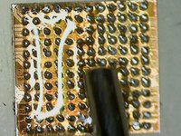
Inspect the card under the microscope. We can see on the picture that a track is missing!
-
-
-
If we compare to the diagram on the PhoneBoard software;
-
We observe very clearly that we will be able to put a wire to redo this connection, focusing on R1103.
-
-
-
Take copper wire with a diameter of 0.02mm
-
Apply flux and tin the wire with an iron.
-
Scratch the trail from C12 to R1103.
-
Laminate this track with tin.
-
Solder one end of the wire to the resistor. I used a 0.01mm diameter tip.
-
Solder the wire along the previously tinned track.
-
Bring the wire into the C12 slot and try to wrap it to be sure that the chip ball will stick to it.
-
-
-
-
The procedure is the same for F12, H12, J12. A12 and B12 are grounded and are not used for U3101 operation, so there is no need to jump them.
-
E12 is in contact with C1, so if C1 is present there is no need to redo this jumper. D12, G12, J11 and A5 are connected to each other, so even if only one is still connected the phone can still function properly. K12, L12, M12 are "No Connection" so there is no need to replace them.
-
-
-
Put on some flux.
-
Take a soldering iron with tin at the end.
-
Pass over the chip to smooth the balls.
-
Clean.
-
Place a reballing stencil over the chip.
-
Spread some soldering paste.
-
Heat with hot air to form the balls.
-
-
-
Extract the chip by pushing with a thin tweezers.
-
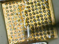
Check the size of the balls.
-
-
-
And finally we put the chip back.Flow, position and solder with hot air.
-
We let the phone cool, test again and the problem is solved!
-


To reassemble your device, follow the instructions in reverse order.
To reassemble your device, follow the instructions in reverse order.
24 の人々がこのガイドを完成させました。
以下の翻訳者の皆さんにお礼を申し上げます:
100%


これらの翻訳者の方々は世界を修理する私たちのサポートをしてくれています。 あなたも貢献してみませんか?
翻訳を始める ›

チーム

7 件のコメント
Are there any micro soldering techs that do business through the mail. I don’t have any close to my area at all that give me wholesale prices any longer, and I am in need BAD!!!! PLEASE RESPOND ASAP! I do mostly iPhones only. Sometimes there are a few oddballs and I live in MA. I need this person to start ASAP. Thanks!
Not sure if you still need help, if you ever need anything for iphone, ipad, or Mac book board repair, try itechcarerepair@gmail.com
Bonjour merci pour le tuto ma question et de savoir quel type d’éteint faut utiliser. Merci
Holy moly, you guys are on a whole other level !!!!
Would replacing the logic board work just as well ?