はじめに
iPhone 5sのフラッシュ、マイク、スリープ/電源ボタンのケーブルを含む上部コンポーネントケーブルを交換するにはこの手順をご利用ください。
この手順ではバッテリーを取り外します。接着ストリップを使ってバッテリーを取り外す方法が一番安全ですが、交換後はバッテリーに接着ストリップが付いていません。バッテリー交換の際には両面テープをバッテリーに装着してください。バッテリーはデバイスの中で固く装着されていますが、テープはガタガタと音が出るのを防いでくれます。
またこの手順を利用して次のパーツも交換できます。ロジックボードのアンテナブラケット、コンタクトクリップ
必要な工具と部品
ビデオの概要
-
-
フロントガラスが割れている場合、ガラスに透明な補強テープを貼りましょう。作業中ガラスが飛び散ったりして怪我をしないようご注意ください。
-
画面全体を何重にも貼り、しっかりと固定します。
-
-
-
この作業でどんなツールを使ってもディスプレイ全体を本体から完全に取り外してください。
-
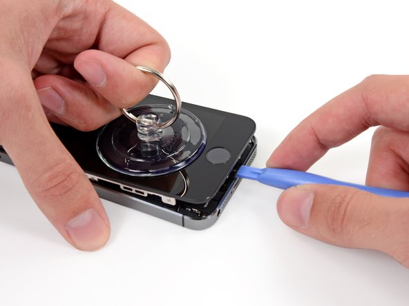
スクリーンが離れてきたら、第1番目の画像にあるように、プラスチック製の開口ツールをフレームとメタル製本体の間に差し込み、ケースからメタルクリップを外します。
-
-
-
青いハンドルを後ろ側に引いて、クランプのアームをロック解除します。
-
iPhoneの右端もしくは左端上にアームをスライドして乗せます。
-
吸盤カップを、ホームボタンすぐ上のiPhoneの下端付近に装着します。上部に一つ、下部に1つずつ取り付けます。
-
両側のカップをしっかりと押し付けて、取り付けたい位置に装着します。
-
-
-
リバースクランプをご利用にならない場合は、フロントパネルを持ち上げるため、シングルタイプの吸盤カップを使います。
-
カップをしっかりとホームボタン上部のスクリーンにしっかりと装着させます。
-
-
-
iPhone を片手でしっかりと抑えながら、吸盤カップを少しずつ引き上げて、本体リアケースからフロントパネルのホームボタン端を引き離します。
-
吸盤カップを引き上げながら、プラスチック製の開口ツールで、ゆっくりとリアケースの端からフロントパネルアセンブリをこじ開けていきます。
-
-
-
ホームボタンケーブルを覆うメタル製ブラケットが取り出せる程度まで本体を開きます。
-
新規購入時のオリジナルのホームボタンアセンブリではTouch IDが使用できます。ケーブルの破損後、新しいホームボタンを取り付けた場合、ホームボタンとしての機能は回復できますが、Touch IDは使用できなくなります。
-
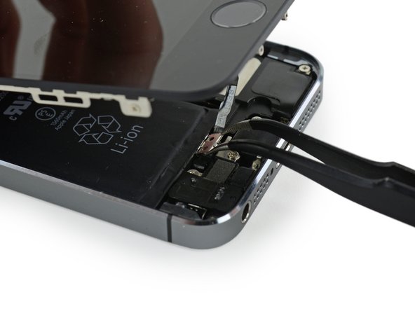
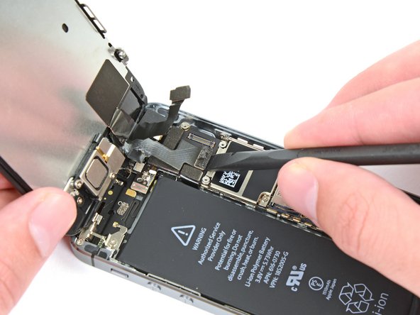
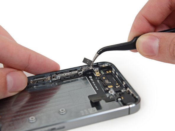
スパッジャーの先端を使ってブラケットを外し、ピンセットで取り出します。
-
-
-
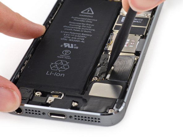
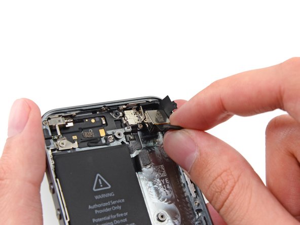
コネクターの接続が外れたら、本体上部を蝶番のようにして、アセンブリのホームボタン先端をリアケースから引き上げます。
-
ディスプレイを約90度で開き、作業中固定するため、ディスプレイの後ろに衝立を用意します。
-
作業中、輪ゴムでディスプレイを固定してください。これはディスプレイケーブルに過度な圧力が加わらないようにするためです。
-
-
-
-
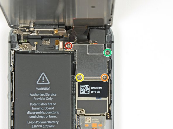
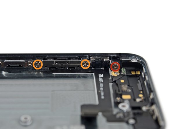
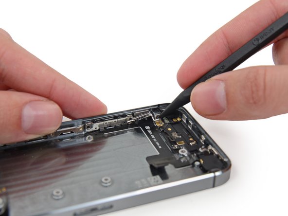
背面ケースの内側に留められたボリュームボタンとリンガースイッチのブラケットから次のネジを取り外します。
-
1.9 mmプラスネジー1本
-
1.6 mmプラスネジー2本
-


デバイスを再組み立てする際は、これらの手順を逆の順番に従って作業を進めてください。
デバイスを再組み立てする際は、これらの手順を逆の順番に従って作業を進めてください。
83 の人々がこのガイドを完成させました。
以下の翻訳者の皆さんにお礼を申し上げます:
100%

これらの翻訳者の方々は世界を修理する私たちのサポートをしてくれています。 あなたも貢献してみませんか?
翻訳を始める ›


7 件のコメント
Parts list calls for:
iPhone 5s Logic Board Grounding Bracket and Contact Clip
not sure why.
Instructions at link for these parts says they are "visible in steps 53 through 56 of the Upper Component Cable Replacement guide". Not quite right.
- Steps 56 & 57 show removal of the Logic Board Grounding Bracket, but instructions call it the “logic board antenna bracket”. Screw that goes through the logic board into this is marked in red on step 30.
- “Small metal contact beneath logic board” referred to in Step 30 goes under the Logic Board Grounding Bracket. See also Step 34.
- Step 59 shows removal of the Contact Clip.
Great guide. Be careful that the silence button is workable before reassembling everything. It is easy to think the switch is in place when it really isn’t. Also, be careful when adhering the new cable to the housing as accurate alignment is essential for the cable to not have a significant kink in it when trying to align it with the logic board. I found that following the markings on the back housing were pretty close when adhering the cable and deciding where to put it. I got sick of messing with battery adhesives and tried to use none and the battery is totally stable once the phone is reassembled and doesn’t rattle around at all.
Quick question: Is this cable compatible with iPhone 5 SE A1723?
mithm_2009 - 返信
Brilliant. My only comments are that it doesn’t mention that the new replacement ribbon cable has adhesive strips that need to be used, so be very careful in the positioning of it before sticking it down. Also, the power button part of the new cable needs to be stuck unto the retaining bracket with glue which you need to have at hand. I used UHU as it is fairly inert and can be easily repositioned. Finally, I suggest you will probably need a magnifier of some kind (stand or glasses) to help in this repair as it is a lengthy process, and best taken slowly.
Great guide! The steps were clear and detailed enough for me to replace upper component ribbon without messing anything else up (which, unfortunately, sometimes does happen) :) The only small thing that I would perhaps mention is that the rubber camera bumper also comes attached to the replacement ribbon, so you don’t have to worry about the old one when you’re removing it. Same with the small strip of adhesive that is holding the contact clip - I recommend removing it since the replacement ribbon also has the same adhesive strip already attached to it.