必要な工具と部品
-
-
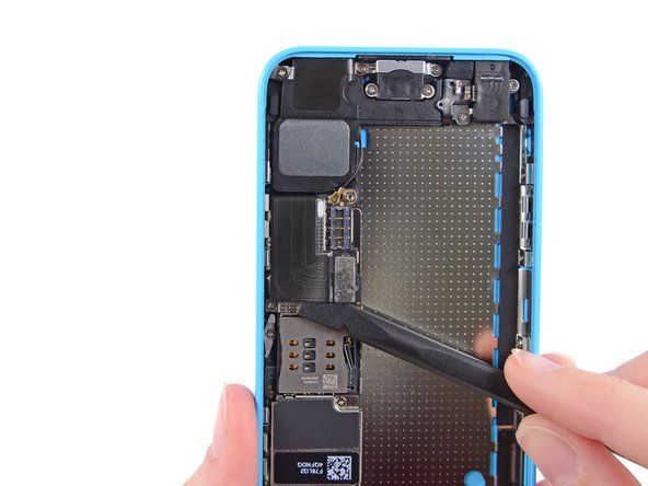
スパッジャーを使って、ロジックボード上のソケットからLightningコネクタリボンケーブルの接続を外します。
-
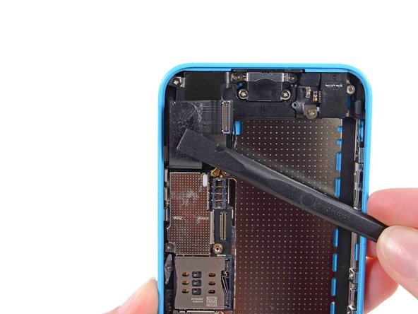
Lightningコネクタケーブルはロジックボード上のシールドに軽く接着剤で留められています。スパッジャーの平面側先端を使って、丁寧にケーブルを剥がします。
-
-
-
-
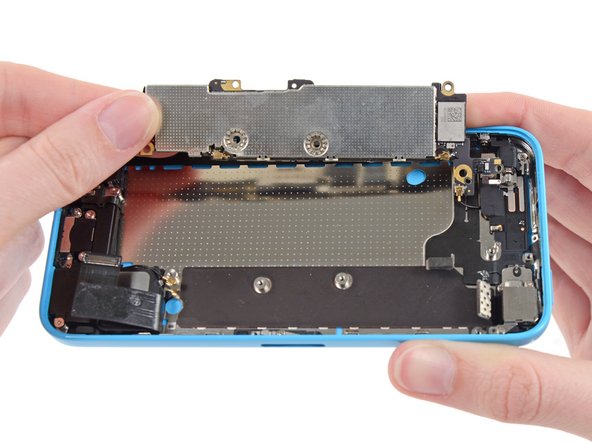
デバイス本体を水平に持ちながら、ロジックボードの底側先端を指で摘めるぐらいまで持ち上げます。
-
ボード先端の下に隠れたゴールドのコンタクトキャップが露出するまでロジックボードを持ち上げます。
-
リアケースのねじ付きポストからゴールドのコンタクトキャップを取り外し、脇に置きます。
On reassembly, it was tricky for me to figure out where the gold clip went. It goes against the back case, upside down and holds the logic board grounding clip, mentioned in Step 34. The upper hole of the grounding clip goes into the gold one, with the opening of the gold one oriented to the right. The 1.2 mm Phillips #000 in the top side-wall, removed in Step 33, holds them both together.
-
-
-
ロジックボードを音量コントロールボタン側に持ち上げて裏返し、アンテナコネクタを露出させます。
On this step, a small threaded barrel came off of the bottom of the housing, once I lifted off the logic board. Upon reassembly, it goes back in with the tiny threaded part down, into the silver piece near the rear facing camera. There is a little hole in the silver to receive it. When the logic board goes back down it matches up with a small silver hole and then secured to the rear case with the 2.7 mm standoff screw furthest to the left in the photo in Step 35. Take care not to put the barrel in upside down because it is very hard to get unscrewed once placed incorrectly.
-


デバイスを再組み立てする際は、このインストラクションを逆の順番に従って作業を進めてください。
デバイスを再組み立てする際は、このインストラクションを逆の順番に従って作業を進めてください。
以下の翻訳者の皆さんにお礼を申し上げます:
100%

Midori Doiさんは世界中で修理する私たちを助けてくれています! あなたも貢献してみませんか?
翻訳を始める ›
