必要な工具と部品
ビデオの概要
-
-
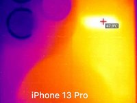
In the first place, we benchmark iPhone 13 Pro and iPhone 12 Pro at the same time. Through LINCSEEK Infrared Thermal Camera, it is found that iPhone 13 Pro gets hotter than iPhone 12 Pro. iPhone 13 Pro can reach a maximum temperature of around 48 °C while the maximum temperature of iPhone 12 Pro is around 40 °C.
-
-
-
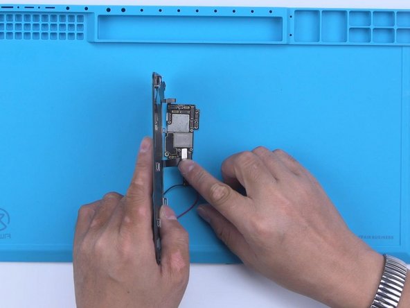
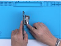
Then we separate the motherboard of iPhone 13 Pro to view its interior structure and find out what has caused the overheating. In the meantime, we will walk you through how to separate and recombine the motherboard.
-
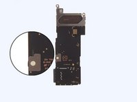
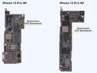
iPhone 13 Pro's motherboard is designed to be more compact to leave more room for the battery. Furthermore, the motherboard no longer uses an L-shaped design.
-
-
-
-
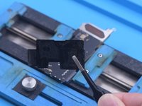
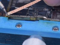
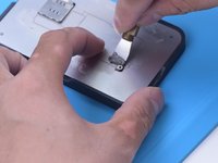
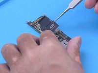
Continue to remove tapes on the back of the motherboard. Heat dissipation tapes on the motherboard are reusable. Please do not damage the tapes during repair to avoid influencing the heat dissipation effect after assembly.
-
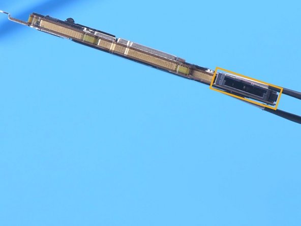
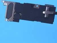
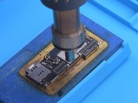
We found that the back of iPhone 13 Pro’s signal board has components. Please pay attention not to damage the components while separating.
-
-
この手順で使用する道具:Tweezers$4.99
-
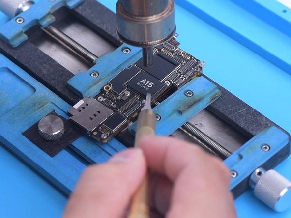
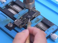
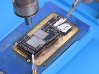
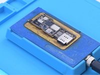
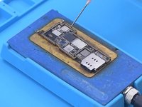
Since the heating platform for iPhone 13 Pro has not come out yet, we use a universal heating platform at 170 °C for separation. Because the middle layer of iPhone 13 lineup’s motherboard still uses middle-temperature Solder Paste for soldering.
-
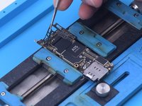
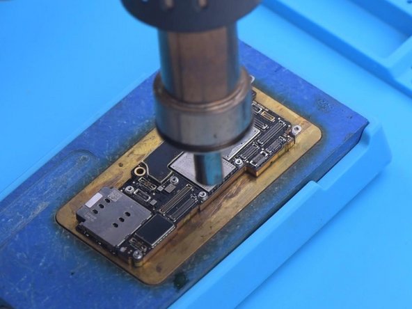
Add heat with Hot Air Gun at 330 °C around the motherboard, when the temperature of the Heating Platform reaches 150 °C. As the logic board becomes loose, remove the logic board with tweezers.
-
The CPU is stacked with the baseband which is bad for motherboard heat dissipation.
-
-
-
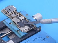
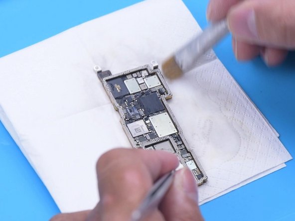
Then we recombine the signal board with the logic board. Apply some Paste Flux to the bonding pads of the signal board.
-
Clean the bonding pads with Soldering Iron at 380 °C and solder wick. Apply solder paste to the bonding pads of the logic board. Please do not affect surrounding components while applying solder paste. This should also be noted while using Soldering Iron to remove tin.
-
Clean the bonding pads with PCB Cleaner.
-
-
-
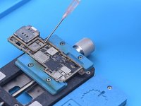
Then we reball the signal board. Attach the signal board to the Reballing Platform. Put the reballing stencil in position. Apply middle-temperature Solder Paste evenly.
-
Remove the reballing stencil. Put the signal board on the Heating Platform to heat. After the solder balls are formed, cool the signal board.
-


To reassemble your device, follow these instructions in reverse order.
To reassemble your device, follow these instructions in reverse order.
3 の人々がこのガイドを完成させました。
