メインコンテンツにスキップ

iMac Intel 24" EMC 2111 Front Bezel Replacement

必要条件のみ
この修理ガイドは、他のガイドの前提条件として使用されます。それ自体は不完全で、単独で使用されることはありません。

必要な工具と部品

  1. iMac Intel 24" EMC 2111 Front Bezel Replacement, Front Bezel: 手順 1、 1の画像 1
    • Remove the following screws along the lower edge of your iMac:

    • Three 6 mm T8 Torx screws

    • One 8 mm T8 Torx screw

  2. iMac Intel 24" EMC 2111 Front Bezel Replacement: 手順 2、 2の画像 1 iMac Intel 24" EMC 2111 Front Bezel Replacement: 手順 2、 2の画像 2
    • Lay your iMac stand-side down on a flat surface.

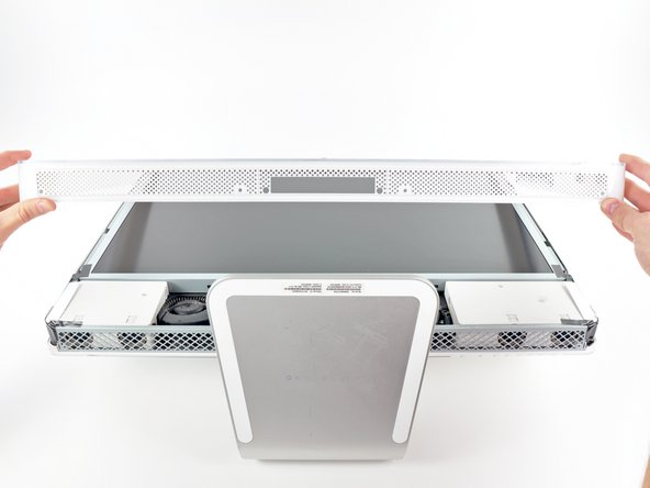
    • To lift the front bezel off the iMac, simultaneously:

    • Use your thumbs to press in the RAM arms and hold the iMac down.

    • Use your index fingers to pull the small bridge of material on the front bezel toward yourself.

    • Pull the front bezel up with your index fingers.

    • Once the small bridge of material has cleared the RAM arms, lift the front bezel by its lower edge just enough to clear the bottom edge of the rear case.

  3. iMac Intel 24" EMC 2111 Front Bezel Replacement: 手順 3、 3の画像 1 iMac Intel 24" EMC 2111 Front Bezel Replacement: 手順 3、 3の画像 2 iMac Intel 24" EMC 2111 Front Bezel Replacement: 手順 3、 3の画像 3
    • Lift the front bezel off the rear case and rotate it away from the bottom edge of the iMac, minding the camera and microphone cables still attached to its upper edge.

    • The third picture shows the top front bezel brackets and their slots cut into the top edge of the iMac's rear case.

    • Do not completely remove the front bezel, as it is still attached by the camera/microphone cables.

  4. iMac Intel 24" EMC 2111 Front Bezel Replacement: 手順 4、 1の画像 1
    • If necessary, remove the strip of tape covering the microphone cable connector.

    • The microphone connector is located near the inside of top edge of your iMac.

  5. iMac Intel 24" EMC 2111 Front Bezel Replacement: 手順 5、 3の画像 1 iMac Intel 24" EMC 2111 Front Bezel Replacement: 手順 5、 3の画像 2 iMac Intel 24" EMC 2111 Front Bezel Replacement: 手順 5、 3の画像 3
    • Disconnect the microphone cable.

    • Disconnect the camera cable by pulling its connector away from the socket on the camera board.

    • The camera cable connector and socket are delicate and easily bent. Remove with caution.

終わりに

To reassemble your device, follow these instructions in reverse order.

作成者

4人の作成者と共同で作成されました。

Andrew Bookholt

586,239 ポイント

619のガイドは作成済み

0 件のコメント

コメントを追加

統計データ:

過去 24時間: 0

過去 7 日: 0

過去 30 日: 0

今までの合計 266