このバージョンは誤った内容を含んでいる可能性があります。最新の承認済みスナップショットに切り替えてください。
必要な工具と部品
-
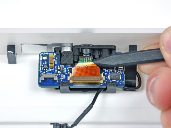
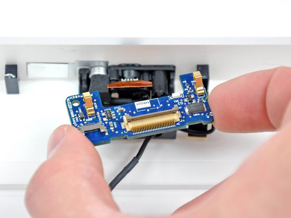
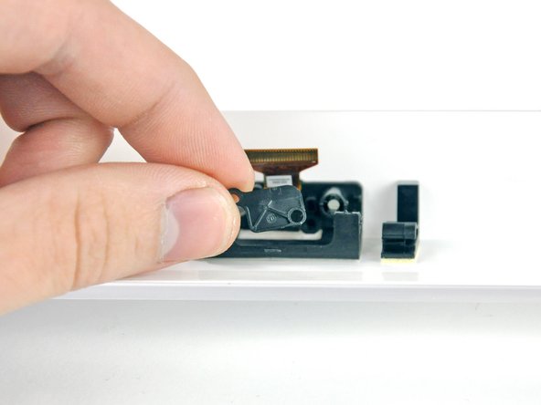
この手順は未翻訳です。 翻訳を手伝う。
-
Remove the following screws along the lower edge of your iMac:
-
Three 6 mm T8 Torx screws
-
One 8 mm T8 Torx screw
-
-
この手順は未翻訳です。 翻訳を手伝う。
-
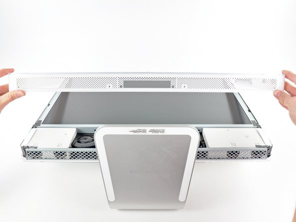
To lift the front bezel off the iMac, simultaneously:
-
Use your thumbs to press in the RAM arms and hold the iMac down.
-
Use your index fingers to pull the small bridge of material on the front bezel toward yourself.
-
Pull the front bezel up with your index fingers.
-
Once the small bridge of material has cleared the RAM arms, lift the front bezel by its lower edge just enough to clear the bottom edge of the rear case.
-
-


もう少しです!
ゴール
