メインコンテンツにスキップ

iMac Intel 21.5" EMC 2805 Logic Board Assembly Replacement

必要条件のみ
この修理ガイドは、他のガイドの前提条件として使用されます。それ自体は不完全で、単独で使用されることはありません。

必要な工具と部品

  1. iMac Intel 21.5" EMC 2805 Logic Board Assembly Replacement, Logic Board Assembly: 手順 1、 2の画像 1 iMac Intel 21.5" EMC 2805 Logic Board Assembly Replacement, Logic Board Assembly: 手順 1、 2の画像 2
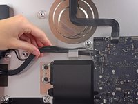
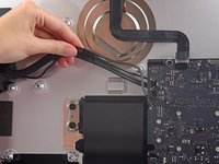
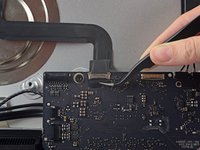
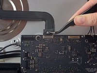
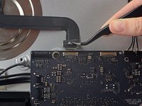
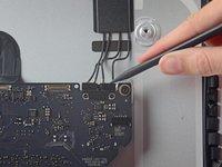
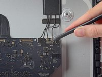
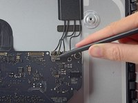
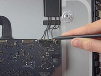
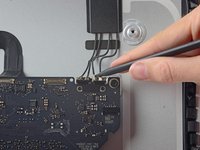
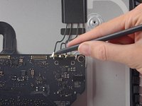
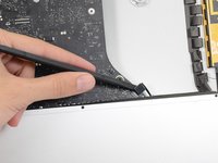
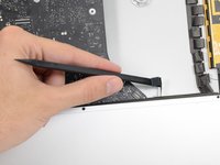
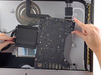
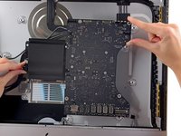
    • Use the tip of a spudger to walk the left speaker cable connector out of its socket.
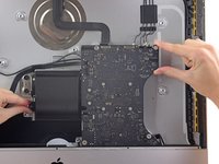
    • It is recommended to first press on one side of the connector, then press on the other side until freed.

  2. iMac Intel 21.5" EMC 2805 Logic Board Assembly Replacement: 手順 2、 1の画像 1
    • De-route the left speaker cable by pulling it straight up out of the retaining clip in the back of the rear enclosure.

  3. iMac Intel 21.5" EMC 2805 Logic Board Assembly Replacement: 手順 3、 2の画像 1 iMac Intel 21.5" EMC 2805 Logic Board Assembly Replacement: 手順 3、 2の画像 2
    • In a similar fashion as the previous step, de-route the combo SATA data/power cable up out of the retaining clip.

  4. iMac Intel 21.5" EMC 2805 Logic Board Assembly Replacement: 手順 4、 3の画像 1 iMac Intel 21.5" EMC 2805 Logic Board Assembly Replacement: 手順 4、 3の画像 2 iMac Intel 21.5" EMC 2805 Logic Board Assembly Replacement: 手順 4、 3の画像 3
    この手順で使用する道具:
    Tweezers
    $4.99
    • Use a pair of tweezers to flip up the metal retaining bracket on the iSight camera cable connector.

    • Pull the iSight camera cable straight out of its socket on the logic board.

    • This is a delicate connector that can be easily damaged.

  5. iMac Intel 21.5" EMC 2805 Logic Board Assembly Replacement: 手順 5、 3の画像 1 iMac Intel 21.5" EMC 2805 Logic Board Assembly Replacement: 手順 5、 3の画像 2 iMac Intel 21.5" EMC 2805 Logic Board Assembly Replacement: 手順 5、 3の画像 3
    • If necessary, use the tip of a spudger to peel back the tabs covering the antenna connectors.

  6. iMac Intel 21.5" EMC 2805 Logic Board Assembly Replacement: 手順 6、 3の画像 1 iMac Intel 21.5" EMC 2805 Logic Board Assembly Replacement: 手順 6、 3の画像 2 iMac Intel 21.5" EMC 2805 Logic Board Assembly Replacement: 手順 6、 3の画像 3
    • Use the tip of a spudger to disconnect each of the four antenna connectors from the AirPort/Bluetooth card.

    • Note the original positions for each connector when reconnecting the cables.

  7. iMac Intel 21.5" EMC 2805 Logic Board Assembly Replacement: 手順 7、 3の画像 1 iMac Intel 21.5" EMC 2805 Logic Board Assembly Replacement: 手順 7、 3の画像 2 iMac Intel 21.5" EMC 2805 Logic Board Assembly Replacement: 手順 7、 3の画像 3
    • Use the flat edge of a spudger to pry the headphone jack cable connector from its socket on the logic board.

    • Push the cable slightly to the right.

  8. iMac Intel 21.5" EMC 2805 Logic Board Assembly Replacement: 手順 8、 1の画像 1
    • Remove the following screws securing the exhaust duct to the rear enclosure:

    • Two 6.3 mm T8 screws

    • Two 4.7 mm T8 screws

  9. iMac Intel 21.5" EMC 2805 Logic Board Assembly Replacement: 手順 9、 1の画像 1
    • Remove the four 7.2 mm T10 screws securing the logic board to the rear enclosure.

  10. iMac Intel 21.5" EMC 2805 Logic Board Assembly Replacement: 手順 10、 1の画像 1
    • Use a pair of tweezers to peel the tape covering the exhaust duct.

  11. iMac Intel 21.5" EMC 2805 Logic Board Assembly Replacement: 手順 11、 2の画像 1 iMac Intel 21.5" EMC 2805 Logic Board Assembly Replacement: 手順 11、 2の画像 2
    • Tilt the top of the logic board away from the rear enclosure.

  12. iMac Intel 21.5" EMC 2805 Logic Board Assembly Replacement: 手順 12、 2の画像 1 iMac Intel 21.5" EMC 2805 Logic Board Assembly Replacement: 手順 12、 2の画像 2
    • Lift the logic board straight up and out of the iMac.

    • Be careful not to snag the board on any of the rear case's screw posts.

    • The I/O inputs at the bottom of the logic board will be the greatest challenge. It is recommended to pull gently to avoid any damage.

  13. iMac Intel 21.5" EMC 2805 Logic Board Assembly Replacement: 手順 13、 2の画像 1 iMac Intel 21.5" EMC 2805 Logic Board Assembly Replacement: 手順 13、 2の画像 2
    • When reinstalling the logic board, check the alignment of the exterior I/O ports. The logic board can sit crooked even when secured with all its screws.

    • Use a USB flash drive and/or ethernet cable to keep the logic board aligned while you screw it in.

終わりに

To reassemble your device, follow these instructions in reverse order.
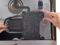
作成者

2人の作成者と共同で作成されました。

Walter Galan

701,042 ポイント

1,203のガイドは作成済み

0 件のコメント

コメントを追加

統計データ:

過去 24時間: 1

過去 7 日: 1

過去 30 日: 1

今までの合計 72