この修理ガイドは変更されています。最新の未承認バージョンに切り替えます。
はじめに
AirPort/Bluetoothカードの交換をするにはこのガイドをご利用ください。
必要な工具と部品
-
-
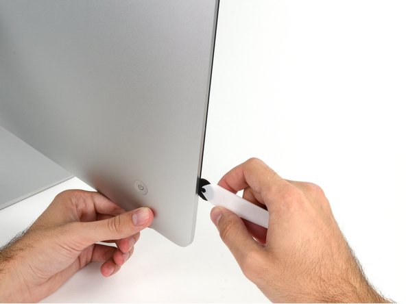
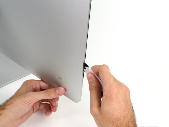
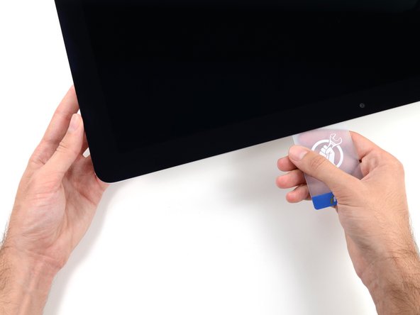
iMac右側の上部から、ディスプレイとフレームの間にプラスチックカードを差し込みます。
So sorry. Thanks for that caution.
Using suction cups (the ones that were made for removing the magnetic front glass on the 2011 and earlier iMacs) work well too. Place one in each top corner, while the Mac is lying face up on a table, and gently pull and it will separate the display from the main body. You might need to do a little more slicing around the edges if you did not get all the way through the first time with the roller. Then you can lift the display up at an angle to disconnect the cables.
This was a great idea, worked well for me. Thanks!
Florin -
-
-
-
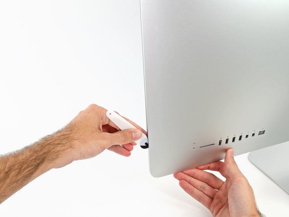
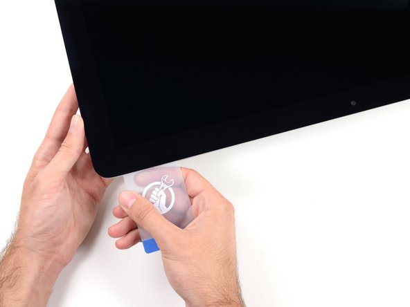
コーナー付近に差し込んだ2枚のプラスチックカードを手に取り、ディスプレイとケースの間の隙間を広げるようにカードを外側に向けてツイストします。
-
フレームからディスプレイ上部を持ち上げます。
-
-
-
The roller tool for slicing open the display works great for this step. Get in there like using the card and roll across the bottom to slice through the remaining adhesive.
-
-
ディスプレイをフレームから持ち上げて、iMacから外します。
-
片一方をゆっくりと持ち上げて、接着剤を剥がしながら外してください。
-
再組み立ての際は、古い接着剤の残りを綺麗に拭き取り、接着ストリップの使用方法を参照してください。iMac Intel 21.5インチ EMC 2544 の接着ストリップの交換ガイドです。
After removing the display, I also removed the 3 screws for the processor fan, disconnected the power connector for it and set the fan shroud aside. Disconnecting the remaining cable (similar style to 1 of the cables for the display) that is in the way of the RAM chips is all that's left to do. I was then able to access and quickly remove the two Apple-provided RAM chips, and replace them with 3rd party RAM. Turning the iMac on its side, so that it's in a position where you're physically putting the RAM chips DOWNWARD into their respective slots is the best way to go about uninstalling and reinstalling the chips. Using a narrow but long'ish plastic spudger tool is the best way to defeat the spring-tabs which hold the RAM chips in place. After removing the LCD display, changing the RAM is about a 10 minute process!! And I'd SURE prefer not to remove all the parts and risk damage to the iMac via the standard procedure listed. As per usual, take your time and work gently :-)
Teardown the whole machine just to change RAM? While preparing to comment on this procedure I just noticed the comment made by Mitch K above. I ran pretty much the same procedure that he describes this afternoon (steps 1-23, 43-45, and step 55). Then I swapped out the original 2x4GB RAM chips for 2x8GB chips by reaching behind the logic board, releasing the spring retaining clips one chip at a time (starting with the chip further away from the logic board), pivoting the RAM towards the back of the machine, and then carefully sliding it out of the slot. I easily slid in the new chips and then pivoted them to lock them down. No hassle, no time lost. As Mitch K states above, not only is this “shortcut” method much quicker and easier, but it provides less risk of damaging cables, sockets and other delicate components during a total teardown. Why mess with the power supply board just to change RAM? I do not advise to follow the current iFixit.com procedure written by Sam Lionheart, regardless of user skill-level.
THAT sounds one !&&* of a lot easier than the full tear down. I wonder if there’s a video of the process described by Mitch K? Adding that to these verbal instructions would really help relieve the apprehension and anxiety around the process! I do sometimes find the additional warnings, though appreciated from a “safety first” perspective, are somewhat overstated. It’s been a very long time since I shorted out RAM, or fried a PCB, or broke a connector, regardless of how finicky, fragile or awkwardly designed and positioned. I may have WANTED to break something, and the air might be blue for a few seconds, but inevitably, things go back together, the start button gets pressed, the startup chime sounds, and we’re in business. Practice DOES make as close to perfect we are likely to get.
Mitch has the exact method that works a treat. You don’t need to follow steps 24-37 and also 40-63. Step 51 is the step to remove the camera cable and is needed. Steps 38 and 39 are for the Fan. That is all that is needed. Done quite a few like this.
Be careful not to drop the RAM down the back of the logic board!
By NOT removing all the other stuff you can avoid either damaging it or forgetting to plug in a cable.
I just trued this shortcut and it was not successful. I was not able to seat both RAM chips with this shortcut, and managed to slightly damage one of the retainer clips. I simply could not manipulate the chips into and out of the slots effectively without taking everything apart as described in the full set of steps.. I ended up retracing my steps and following the entire procedure, carefully, and that worked without incident. So, bottomline, it is definitely more work to follow all the steps but from my experience, it is decidedly safer. Your mileage may, of course, vary. It was successful in the end, and I swapped out the hard drive with an ssd during the same procedure and my machine is very, very much faster.
I have completed by following the Mitch K post and it is much easier than stripping down the whole thing, just be aware that to remove and replace the ram chips means working in a tight space, you need slim fingers and don’t be tempted to use force, take your time.
Well, I have slim fingers, but they are 60 years old, and they don’t work like they used to! LOL.
Agree with Mitch K’s procedure. The only added tip I would throw in is to use two 45 degree tweezers with their plastic covers still installed to easily pop loose the RAM. I couldn’t get the plastic spudger tool to work myself, but the tweezers easily reach the RAM clips. Just make sure the plastic covers are installed and you won’t be in danger of scratching or shorting anything out.
So thankful I discovered these comments. Saved me a TON of time! Thank you!!
These comments were very useful. Thank you. I just needed to modify a pair of tweezers to allow me to seat the new RAM more easily. The ifixit screwdriver wasn't able to turn some of the screws as they were installed too tightly, and I didn't want to wait to order and reveive a pair of right angled Torx screwdrivers that would give me more leverage to get those boards off.
-
-
-
スパッジャーを使って、基板上のソケットから右側スピーカーのケーブルコネクターの接続を緩めます。
-
コネクターを下向きに押し込んで、ソケットから外します。
I highly recommend doing steps 27 and 28 first and then pull out the cable. It will give you more room on the right side of the cable to work with making this step that much easier.
The two corners of the connector are latches that need to be pushed toward the center of the connector to release. This is easily done with the pointed end of the spudger. Once the two corner latches are released, the connector comes apart easily.
-
-
-
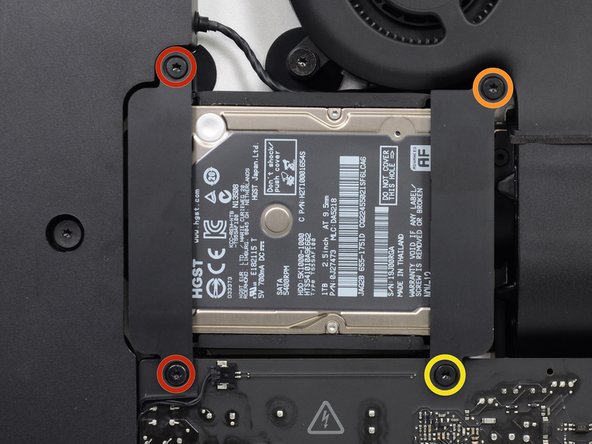
リア筐体にハードドライブブラケットを固定している次のネジを外します。
-
左側ハードドライブブラケットから21 mm T10トルクスネジー2本
-
9 mm T10トルクスネジー1本
-
27 mm T10 トルクスネジー1本
Pay attention to this photo and where the fan is. It is 180° from where the previous step shows it is oriented to you.
Max Romano - 返信
-
-
-
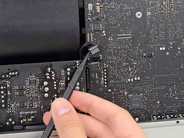
スパッジャーの先端を使って、パワーボタンケーブルコネクターの両側を押さえて、ソケットから丁寧に”ずらしながら”外します。
-
-
-
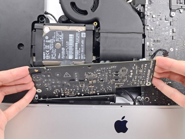
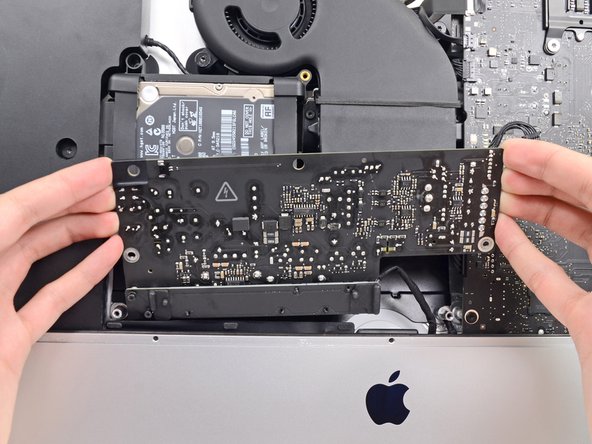
裏側の筐体にパワーサプライを固定している7.2 mm T10ネジを2本外します。
What if these are too tight to remove?
Hi Rafael,
Be very careful not to strip these screws. Use a new, accurate T10 bit and a driver with good leverage to loosen these screws.
They are T9 in my iMac
They were T8 screws on my machine.
-
-
-
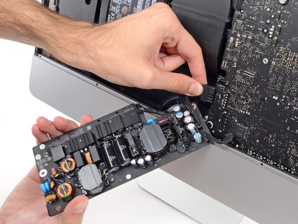
DCパワーケーブルコネクターのタブをつまんで、基板の裏側にあるソケットからまっすぐ引っ張り出します。
what happens if you damage the power socket on the logic board?
The tab is on the bottom of the connector. You can’t see it. Squeeze the bottom of the connector close to the cables to properly release tab. Pulling straight out is important.
This step might be easier if you do the next step first (step 41) and then come back to this step.
I loosened the logic board attached to the power supply board. I then could easily remove the 2 power cables.
In the photo above, the index finger is shown squeezing the connector locking tab. Do this while using the flat end of a spudger to release the latch. Once the connector is moved about an eigth of an inch the latch is released and the connector should come out freely.
-
-
-
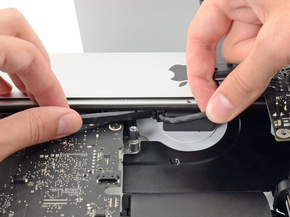
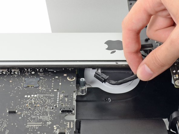
ファンケーブルコネクタを基板上のソケットからまっすぐ丁寧に引き抜きます。
I don’t like to pull on wires as shown in the photos above. I used my index fingernail on the top corner of the connector and the pointed end of a spudger on the bottom corner to pull the connector straight out of its socket.
-
-
-
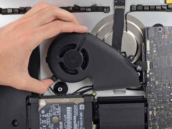
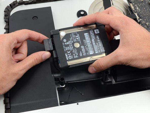
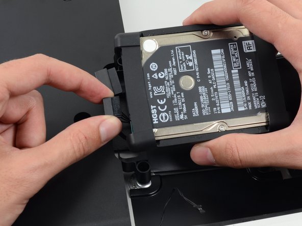
リアエンクロージャーにハードドライブトレイを固定している7.2 mm T10ネジを1本外します。
-
-
-
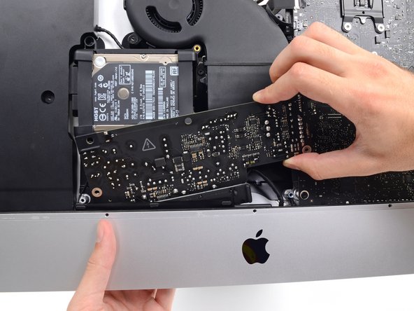
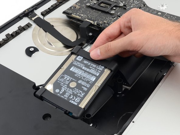
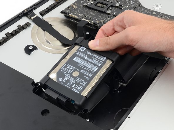
リアエンクロージャーからハードドライブトレイを取り出します。
Cables are routed through the backside of the tray. Take a picture for reassembly.
-
-
-
左側スピーカーのケーブルコネクタの各サイドをスパッジャーの先端で押し込んで、ソケットから丁寧に外していきます。
As noted in the right speaker cable section, the two corners of the connector are latches that need to be pushed toward the center of the connector to release. This is easily done with the pointed end of the spudger. Once the two corner latches are released, the connector comes apart easily.
-
-
-
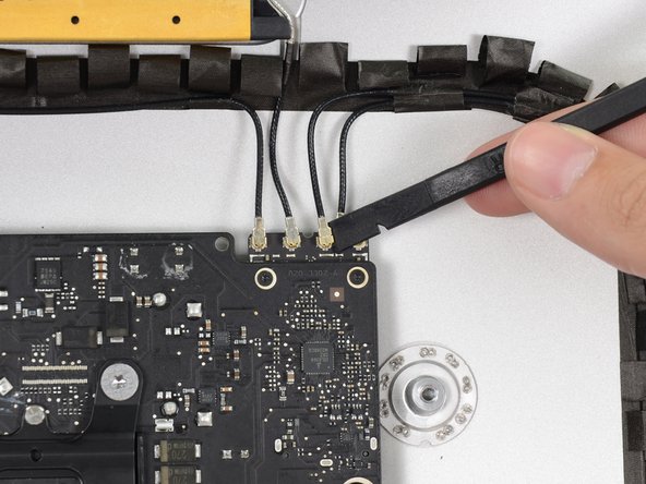
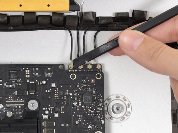
スパッジャーの平面側先端を使ってAirPort/Bluetoothカードから4本のアンテナコネクタの各接続を外します。
I broke off one of the antenna connectors when I took off the antenna wires, but the new 802.11ac card is working:) I seems the way to take off the wires is lifting it up from the wire side. In hindsight I just wasn´t careful enough.
how do I check a working logic board
If you have a pair of angled tweezers, they work well for grabbing under the connector so that you aren’t pulling on the wire. The head of the T10 screwdriver works well for pressing them back on.
iMac 2017 EMC 3069 this has the antenna brackets with two T5
-
-
-
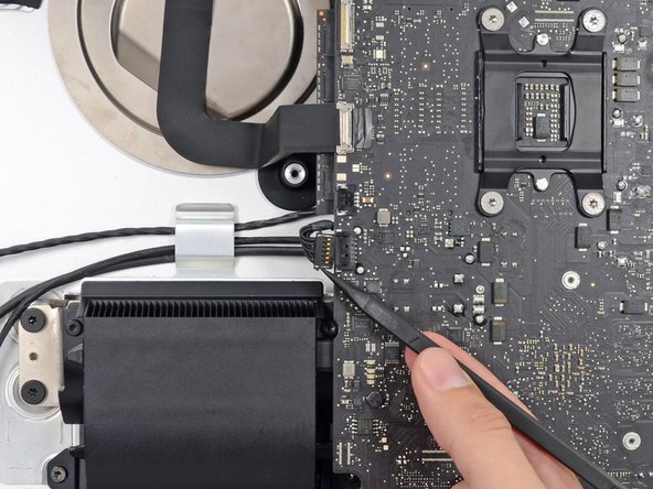
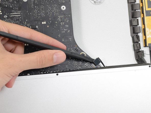
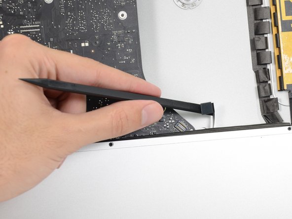
スパッジャーの平面側先端を使って、ロジックボード上の基板からヘッドホンジャックのケーブルコネクタを引き抜きます。
Unlike the rest of the connectors on the logic board, this one lifts up away from the board rather than to the side. That “Push the cable slightly to the right.” notation is after the connector is free.
-
-
-
リアエンクロージャーに排気ダクトを固定している次のネジを外します。
-
6.3 mm T8ネジー2本
-
4.7 mm T8ネジー2本
Weirdly, these screws didn’t work with my T8 driver. Not with T6 or T10.
Every other screw (to this point) has been fine. Hmm.
??? The T8 worked fine for me. Not sure what the difference would be.
Fare molta attenzione alla vite in fondo a destra, è facile (soprattutto se la punta del proprio cacciavite non è magnetizzata) che la vite si perda sotto alla Logic board. Se la punta del cacciavite non è magnetizzata consiglio o di utilizzare un magnete esterno o di utilizzare delle pinze mentre si svita la vite in modo da non incorrere in questo problema.
-
-
-
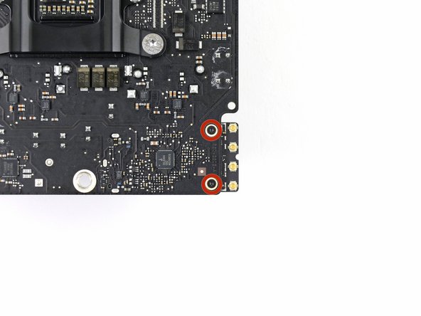
リアエンクロージャーにロジックボードを固定している7.2 mm T10ネジを4本外します。
When reinstalling the logic board, install four screws loose. Insert thumb drives into the back in all slots to ensure alignment. Once aligned, then tighten screws.
Gary Kelch - 返信
On some models there is a tiny microphone cable connector, just above the lower left logic board screw. Remove by carefully pulling straight down. There is also a piece of insulating plastic w/adhesive on top of the screw which can be pulled off prior to removal. Save and reuse with the same screw on installation.
-
-
-
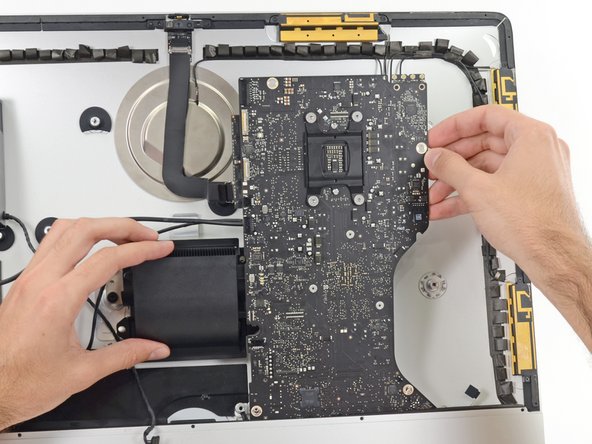
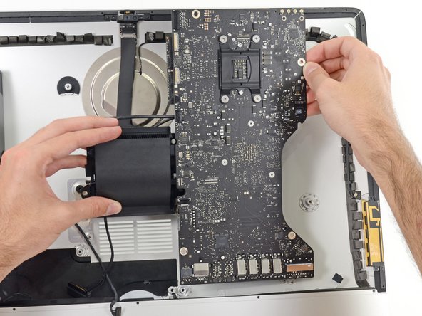
ロジックボードをリアエンクロージャーから離すように傾けます。
-
ロジックボードをiMacからまっすぐ持ち上げて取り出します。
When inserting the logic board back, pay attention of the position of the I/O connectors. When it is back in place, put a USB / Thunderbolt cable into the connectors to ensure the perfect alignment.
This is fantastic advice. I used a combination of USB and display port plugs to ensure proper alignment and help keep the logic board steady while i screwed it back in. Thank you!!
kazoodac -
ive gotten this far and i still have one question, i’m replacing my HDD With A SSD should i also remove the original Blade drive ? and run exclusively off the ssd, ? i wasn’t 100 on whether or not i was getting the fusion set up so i’m not in possession of a upgraded blade, so i though this was a good question id hadn’t seen asked.
-
-
-
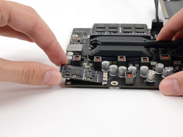
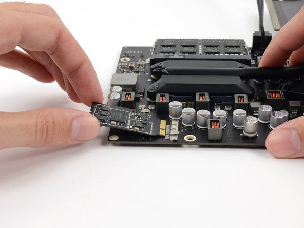
AirPort/Bluetoothカードをソケットからまっすぐ引き抜いて持ち上げます。
I addition to the two Torx5 screws, My Wi Fi bluetooth card was glued to the main board with a grey porous glue that was easy to peel off once I got the card loose.
-


デバイスの再組み立てをする際は、これらのインストラクションを逆の順番に従って作業を進めてください。ディスプレイガラスを再装着する際は 接着ストリップの装着方法を参照してください。
デバイスの再組み立てをする際は、これらのインストラクションを逆の順番に従って作業を進めてください。ディスプレイガラスを再装着する際は 接着ストリップの装着方法を参照してください。
5 の人々がこのガイドを完成させました。
以下の翻訳者の皆さんにお礼を申し上げます:
100%

Midori Doiさんは世界中で修理する私たちを助けてくれています! あなたも貢献してみませんか?
翻訳を始める ›


3 件のコメント
I successfully upgraded the Wi-Fi Bluetooth card in my late 2012 iMac to 802.11ac following this guide! The new card is now the same as what´s in the new 2013 iMacs, I used the 2013 iMac teardown to find the right part:)
I just bought a new BT card (a >2013 version!) and it works!!!! Just some advise before you start: follow the instructions above including step 28. At this point unscrew the big sized mainboard screws. This allows some movement so you can pull back the motherboard if needed and will avoid straining it to much. you can nog pull out the Bluetooth card without dismantling the whole computer! Putting the new card back also works fine this way. This Saves you massive time!
I have (21.5 inch, mid 2017, 2.3 ghz) base model same as this but not 4k. How much max ram can I install in my iMac??
Narendra Verma - 返信
This guide contains many extra steps for what should be a straight forward, simple parts replacement without disturbing more than the display, left hand speaker and removal of 4 logic board screws for play. Nothing else except for the left hand speaker wire & iSight cable from logic board, the lower support bracket and loosening the speaker so as to move it around a bit.
For the ram, I bent a pair of cheap tweezers long ago supplied with these replacement kits to the perfect angle for holding, locating and inserting the ram into the slots under the logic bd after moving each retainer w/spudger and popping out the old. Pay attention to the orientation of the ram when removing/inserting the ram! An automotive mirror is handy along with a small flashlight for closeups. Once the ram is aligned properly substitute your fingers for the tweezers, ease it into the slot, push up & engage! Reinstall screws and all else. I have done this job successfully this way countless times. For a tweezers pic contact me!
Ross Elkins - 返信
Additionally, if a blade is present, I install the OSx system on the blade and everything else, apps and home folders on the new SSD. You get the very fast boot off of the blade and the full ssd for all else!
Ross Elkins - 返信