このバージョンは誤った内容を含んでいる可能性があります。最新の承認済みスナップショットに切り替えてください。
必要な工具と部品
-
この手順は未翻訳です。 翻訳を手伝う。
-
Place your hands at the top corners of the bezel (to the side) and lift the bezel 2-3cm from the body by working from the top. After this you can also disengage the bottom of the bezel (the memory modules will prevent the bottom of the bezel to detach first). When reassembling, start with the bottom of the bezel.
-
To fully detach the bezel: disconnect the microphone cable connector, removing tape as necessary.
-
To keep it attached, leave the microphone cable attached to the logic board, and place the bezel 'above' the chassis, with the microphone cable forming a hinge.
-
-
この手順は未翻訳です。 翻訳を手伝う。
-
be sure to tuck the microphone cable and connector into the void next to the camera board.
-
Gently guide the microphone connector and cables through the ±1in long slot at the right of the iSight camera. Once the bezel is properly assembled, gently push the microphone connector and cable into the bezel through that slot.
-
-
この手順は未翻訳です。 翻訳を手伝う。
-
With the display panel still lifted, disconnect the four inverter cables.
-
If you are replacing a hard drive and have an extra set of hands, it is possible to reach in and remove the drive without disconnecting anything but the LCD temp and display connector in the previous step with the LCD in its propped position.
-
-
-
この手順は未翻訳です。 翻訳を手伝う。
-
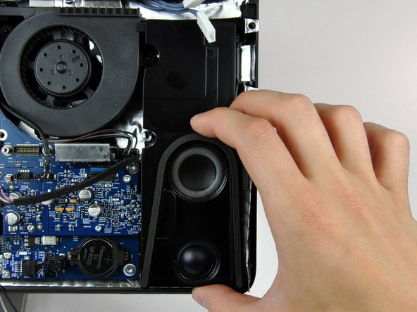
Remove the single 28 mm T10 Torx screw securing the left speaker to the rear case.
-
Lift the left speaker up and out of the rear case. Don't try to slide the speaker out, since there is a plastic mounting pin under the top end of the speaker housing that holds it in place.
-
-
この手順は未翻訳です。 翻訳を手伝う。
-
Remove the following 13 screws securing the logic board to the rear case:
-
Six 7.2 mm coarse-thread T10 Torx.
-
Two 6.8 mm T8 Torx. When reinstalling these two screws, don't overtighten them, as the plastic tabs they hold down are thin and brittle, and can crack.
-
Three 7 mm fine-thread T10 Torx.
-
Two 24 mm T10 Torx.
-


45 の人々がこのガイドを完成させました。

7 件のコメント
Superb instructions. just replaced my iMac 2007 with another motherboard as I had a faulty ram slot and put in a new SSD hard drive. Would have struggled without this step by step guide.
john riley - 返信
Thanks. I was able to successfully replace the logic board following these instructions. I'm not sure I would have been able to do it on my own.
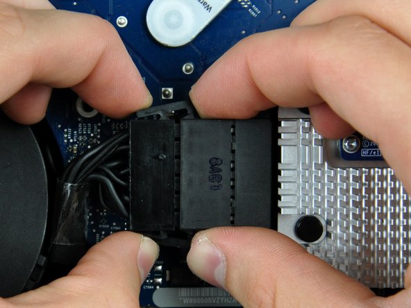
How is named the block right above the ram slots? This thing covered with the bright aluminium « mini-Manhattan » :) (or « porcupine »)?
I thought it was the CPU itself but if I read correctly, CPU is under the 45° structure. Right? Thank you.
I’m sorry for the late answer, but I believe the chip under that heat sink is the North Bridge. It controls data transfer between the CPU, RAM, and graphics.
What is the thing above the ram slots? That thing with the bright aluminium « porcupine » on top of it ;) thank you