The glass panel is fixed onto the front bezel with fourteen magnets around its perimeter.
Stick two suction cups to opposing corners of the glass panel.
To attach the suction cups we sell, first position the suction cup with the movable handle parallel to the face of the glass panel. While lightly holding the suction cup against the glass, raise the movable handle until it is parallel with the other handle.
If your suction cups refuse to stick, try cleaning both the glass panel and the suction cup with a mild solvent such as Windex.
Gently pull the glass panel straight up off the iMac.
The glass panel has several positioning pins around its perimeter. To avoid shearing these pins off the glass panel, be sure to only pull straight up during removal.
Be meticulous about cleaning the LCD and the inside face of the glass panel before reinstallation, as any fingerprints or dust trapped inside will be annoyingly visible when the display is on. Placing the glass flat, inside face down, on a fresh aluminum-foil surface is a good way to keep it clean.
Place your hands at the top corners of the bezel (to the side) and lift the bezel 2-3cm from the body by working from the top. After this you can also disengage the bottom of the bezel (the memory modules will prevent the bottom of the bezel to detach first). When reassembling, start with the bottom of the bezel.
The top of the bezel hosts a microphone attached to the logic board. Gently lift the bezel to not damage the microphone wiring or connector by accidentally pulling the cable.
At this point, you can either detach the microphone cable and remove the bezel, or keep the microphone cable attached and rest the bezel on your work surface or the chassis of the Mac.
To fully detach the bezel: disconnect the microphone cable connector, removing tape as necessary.
To keep it attached, leave the microphone cable attached to the logic board, and place the bezel 'above' the chassis, with the microphone cable forming a hinge.
If you keep the microphone attached to the chassis, make sure you don't accidentally damage the microphone or logic board by bumping into the loose bezel.
be sure to tuck the microphone cable and connector into the void next to the camera board.
Gently guide the microphone connector and cables through the ±1in long slot at the right of the iSight camera. Once the bezel is properly assembled, gently push the microphone connector and cable into the bezel through that slot.
Pull the LCD temperature sensor connector straight up out of its socket on the logic board.
If necessary, de-route the LCD temperature sensor cable from behind the logic board.
When you remove the LCD, check the routing of the LCD temperature display cable. On reinstalling the display, be sure this cable does not block one of the bottom screws for the front bezel.
With the display panel still lifted, disconnect the four inverter cables.
During reinstallation, place the four inverter cable connectors in voids between components attached to the rear panel so the display panel will sit flush.
During reassembly, the order of the inverter cables is interchangeable within each socket.
If you are replacing a hard drive and have an extra set of hands, it is possible to reach in and remove the drive without disconnecting anything but the LCD temp and display connector in the previous step with the LCD in its propped position.
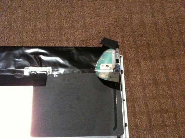
The LCD temperature sensor is located on the rear of the display panel in the top right corner when viewed from the rear. It is under the black foil about 40mm (1 1/2 in) from the top edge of the panel.
Lay the display panel face down on a cleared surface ensuring nothing is under the panel that may damage it.
Carefully cut a small nic in the foil at the top right corner and gently peel back at an angle to expose the sensor. It will have a foam pad stuck over it.
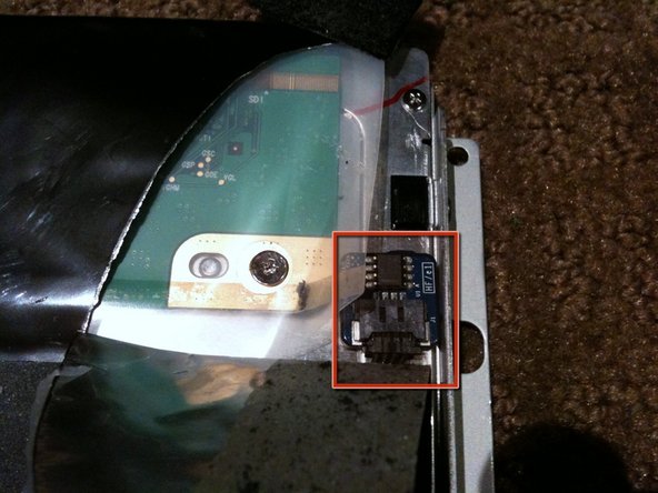
Gently peel the foam off the sensor to reveal the PCB assembly.
The Sensor is held in place with a small adhesive pad so to remove it, gently pry it up from one edge with a plastic spudger or similar. I recommend NOT using metal tools here.
Disconnect the cable to remove the sensor
Quality Tip When installing the sensor, ensure the connector is well seated and you don't put the connector or cable under tension as this may cause them to separate after reassembly of the system
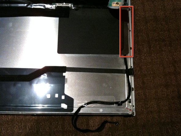
Note the routing of the cable. It runs up the right side of the display panel and under the edge of black plastic PSU guard adhered to the display panel
If you need to replace the cable, gently lift the right edge of the black PSU guard and carefully peel the cable off the adhesive backing on the guard.