The glass panel is fixed onto the front bezel with fourteen magnets around its perimeter.
Stick two suction cups to opposing corners of the glass panel.
To attach the suction cups we sell, first position the suction cup with the movable handle parallel to the face of the glass panel. While lightly holding the suction cup against the glass, raise the movable handle until it is parallel with the other handle.
If your suction cups refuse to stick, try cleaning both the glass panel and the suction cup with a mild solvent such as Windex.
Gently pull the glass panel straight up off the iMac.
The glass panel has several positioning pins around its perimeter. To avoid shearing these pins off the glass panel, be sure to only pull straight up during removal.
Be meticulous about cleaning the LCD and the inside face of the glass panel before reinstallation, as any fingerprints or dust trapped inside will be annoyingly visible when the display is on. Placing the glass flat, inside face down, on a fresh aluminum-foil surface is a good way to keep it clean.
Place your hands at the top corners of the bezel (to the side) and lift the bezel 2-3cm from the body by working from the top. After this you can also disengage the bottom of the bezel (the memory modules will prevent the bottom of the bezel to detach first). When reassembling, start with the bottom of the bezel.
The top of the bezel hosts a microphone attached to the logic board. Gently lift the bezel to not damage the microphone wiring or connector by accidentally pulling the cable.
At this point, you can either detach the microphone cable and remove the bezel, or keep the microphone cable attached and rest the bezel on your work surface or the chassis of the Mac.
To fully detach the bezel: disconnect the microphone cable connector, removing tape as necessary.
To keep it attached, leave the microphone cable attached to the logic board, and place the bezel 'above' the chassis, with the microphone cable forming a hinge.
If you keep the microphone attached to the chassis, make sure you don't accidentally damage the microphone or logic board by bumping into the loose bezel.
be sure to tuck the microphone cable and connector into the void next to the camera board.
Gently guide the microphone connector and cables through the ±1in long slot at the right of the iSight camera. Once the bezel is properly assembled, gently push the microphone connector and cable into the bezel through that slot.
Pull the LCD temperature sensor connector straight up out of its socket on the logic board.
If necessary, de-route the LCD temperature sensor cable from behind the logic board.
When you remove the LCD, check the routing of the LCD temperature display cable. On reinstalling the display, be sure this cable does not block one of the bottom screws for the front bezel.
With the display panel still lifted, disconnect the four inverter cables.
During reinstallation, place the four inverter cable connectors in voids between components attached to the rear panel so the display panel will sit flush.
During reassembly, the order of the inverter cables is interchangeable within each socket.
If you are replacing a hard drive and have an extra set of hands, it is possible to reach in and remove the drive without disconnecting anything but the LCD temp and display connector in the previous step with the LCD in its propped position.
The rest of this procedure should be done in the cleanest possible work environment to avoid dust getting BEHIND the LCD (I learned this the HARD way!)
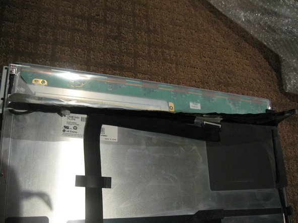
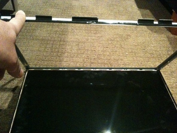
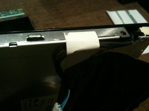
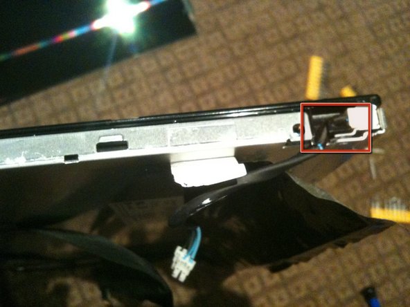
Once the LCD panel is removed you need to peel back the black foil from the top edge of the LCD to reveal the clear plastic PCB protector.
Now gently peel the clear plastic PCB protector off the top edge. Make sure you don't damage the flex cables attached to the PBC you are exposing.
There are a total of 8 flex cables along the top edge
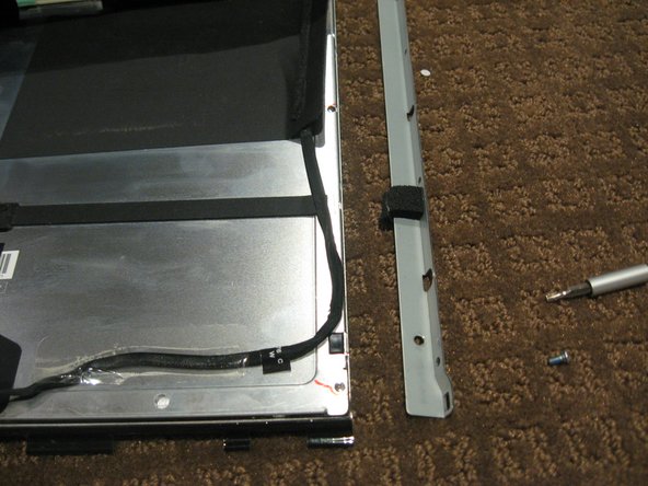
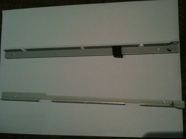
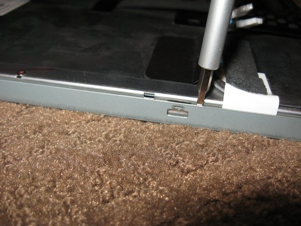
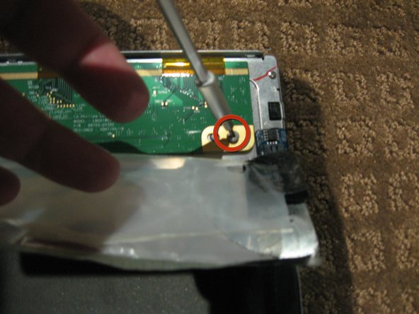
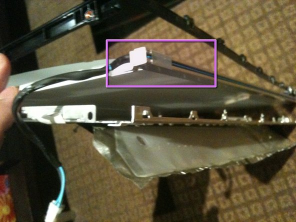
Now gently separate the metal bezel from the main body of the LCD panel
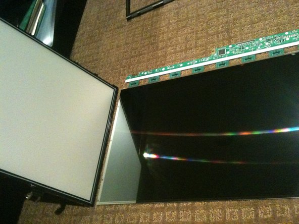
Lay the LCD panel down on with viewing side UP and remove the metal bezel
Make sure you are careful when removing the bezel from the TOP edge as you will be exposing the 8 flex cables mentioned in step 1.
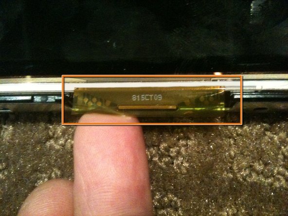
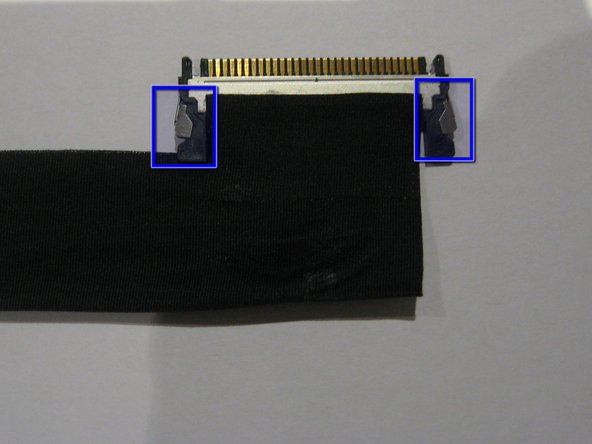
Note the 3 flex tabs on the left edge
Do not damage any of the tabs or flex cables as these are the Row and Column Drivers. Damage to these will will cause faults like vertical/horizontal lines or white screen etc.
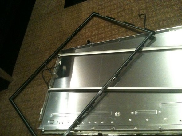
WARNING - Once the bezel is removed the LCD is LOOSE in the black plastic frame - only held in by the small gasket underneath.
Using a plastic spudger or pry tool, work GENTLY around the edges of the LCD to loosen it from the gasket below - use GREAT CARE so you don't crack or chip the panel as it is only a couple mm thick
Once the LCD is loose you need to HOLD it in place in the black plastic frame and GENTLY flip the entire assembly so the LCD is flat on the work surface
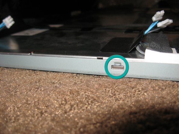
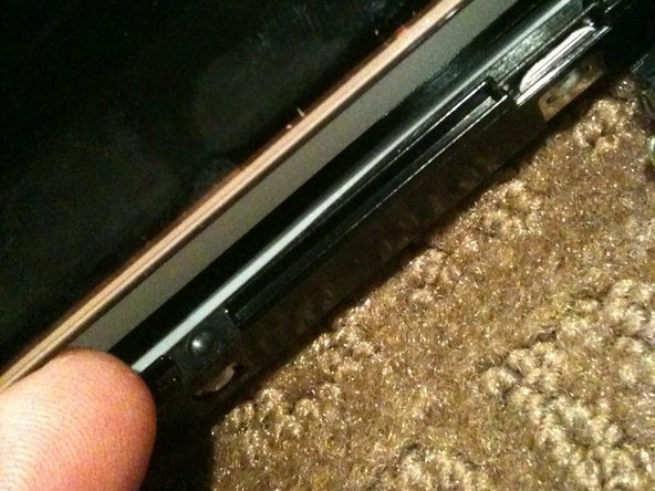
The bottom of the black surround can now be un-clipped and the entire surround removed
There are 4 tabs along the bottom of the assembly
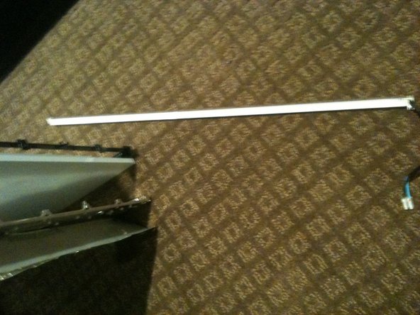
Once the black surround is off the rest pretty much comes apart with the bottom CCFL tube being able to be removed in a similar manner to the top
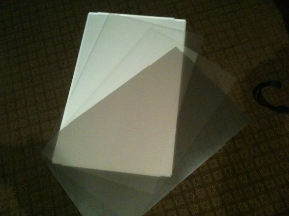
The centre of the back light assembly is made up of 4 main parts. A perspex sheet with white plastic coating, 2 opaque matt plastic sheets, and 1 Pearlescent matt plastic sheet
The plastic sheets are polarisers so need to be kept clean and free of dust and scratches
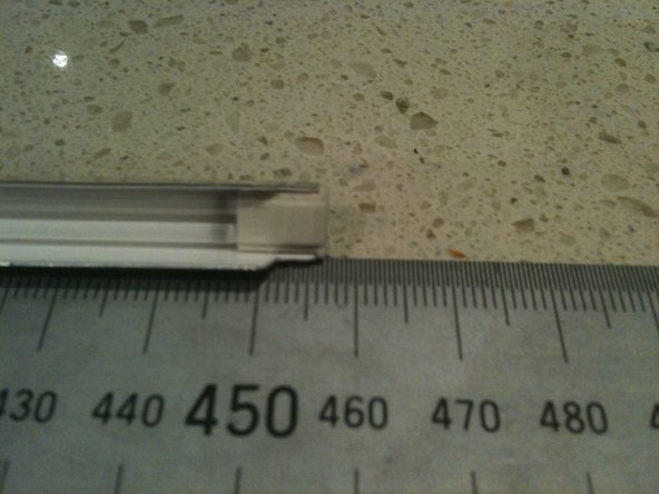
The CCLF tube assemblies are made up of a U shaped reflector with 2ea individual tubes inside. The entire assembly is 457mm long and 7.6mm wide. There are no part numbers on the assembly however there is a S on the end with the wires attached and an 18 on the other end.
The 2 CCFL tubes are held together with a figure 8 rubber band in the middle of the reflector so both tubes must come out at the same time.
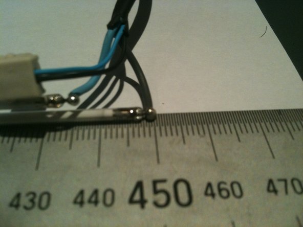
The individual tubes are 448mm long (excluding the terminals - standard way to measure is end of glass to end of glass) and are 2.4mm diameter.
The CCFL are soldered to the wires so not a simple plug in replacement
The CCFL are EXTREMELY fragile so ensure you dont break them when installing them.
The CCFL reflectors are a tight fit over the sides of the perspex sheet and the other layers of plastic. Patience and a plastic spudger or pry tool should get you there
The closest I can find to my CCFL measurements are either the 446mm x 2.4mm or the 450mm x 2.4mm so I'd suggest the 446mm is used