メインコンテンツにスキップ

この翻訳は、ソースガイドの最新の更新を反映していない可能性があります。 翻訳の更新に協力してください。 または ソースガイドを参照してください

必要な工具と部品

  1. , アクセスドア: 手順 1、 2の画像 1 , アクセスドア: 手順 1、 2の画像 2
    • アクセスドアをiMacに固定している脱落防止プラスネジを緩めます。

    • iMacからアクセスドアを取り外します。

    • 作業を開始する前に、コンピュータの電源ケーブルを抜き、電源スイッチを20-30秒間押し続け、本体内部のコンデンサの静電気を放電します。

  2. , フロントベゼル: 手順 2、 1の画像 1
    • 次の4本のネジを外します:

    • 6mm T8トルクスネジ 3本

    • 8mm T8トルクスネジ 1本

  3. この手順は未翻訳です。 翻訳を手伝う。

    : 手順 3、 2の画像 1 : 手順 3、 2の画像 2
    • Flip your iMac over and lay it stand-side down on a flat surface.

    • To lift the front bezel off the iMac, simultaneously:

    • Use your thumbs to press in the RAM arms and hold the iMac down.

    • Use your index fingers to pull the small bridge of material on the front bezel toward yourself.

    • Pull the Front bezel up with your index fingers.

    • Once the small bridge of material has cleared the RAM arms, lift the front bezel by its lower edge just enough to clear the bottom edge of the rear case.

  4. この手順は未翻訳です。 翻訳を手伝う。

    : 手順 4、 3の画像 1 : 手順 4、 3の画像 2 : 手順 4、 3の画像 3
    この手順で使用する道具:
    Plastic Cards
    $2.99
    購入する
    • Re-orient your iMac so it sits upright on the stand.

    • Insert a plastic card up into the corner of the air vent slot near the top of the rear case.

    • Push the card toward the top of the iMac to release the front bezel latch.

    • Pull the front bezel away from the rear case.

    • Repeat this process for the other side of the front bezel.

    • It may be necessary to apply several layers of duct tape to the top of the access card to aid in releasing the latches.

    • If the bezel refuses to release, try pressing the lower edge back onto the rear case and repeat this opening process.

  5. この手順は未翻訳です。 翻訳を手伝う。

    : 手順 5、 1の画像 1
    • Lay your iMac stand-side down on a table.

    • Lift the front bezel from its lower edge and rotate it away from the rest of your iMac, minding the RAM arms that may get caught.

    • Lay the front bezel above the rest of the iMac.

  6. この手順は未翻訳です。 翻訳を手伝う。

    : 手順 6、 1の画像 1
    • If necessary, remove the piece of kapton tape(it is ok to toss this) wrapped around the microphone and camera cables.

  7. : 手順 7、 2の画像 1 : 手順 7、 2の画像 2
    • カメラとマイクケーブル両方の接続を外します。

  8. この手順は未翻訳です。 翻訳を手伝う。

    : 手順 8、 1の画像 1
    • Peel up the lower EMI shield from the rear case.

    • It is only necessary to peel the shield up from three sides. Leave it attached to the display.

    • We have found it helpful to tape the EMI shield against the display to keep it out of the way.

  9. この手順は未翻訳です。 翻訳を手伝う。

    : 手順 9、 2の画像 1 : 手順 9、 2の画像 2
    • Remove the two 4.8 mm T6 Torx screws securing the display data cable to the logic board.

    • Grab the display data cable connector by its black tab and pull it straight up off the logic board.

  10. この手順は未翻訳です。 翻訳を手伝う。

    : 手順 10、 1の画像 1
    • Inverter cable on 24inch iMac pulls off to the left.

    • Pull the inverter cable connector straight up off its socket on the logic board.

  11. この手順は未翻訳です。 翻訳を手伝う。

    : 手順 11、 1の画像 1
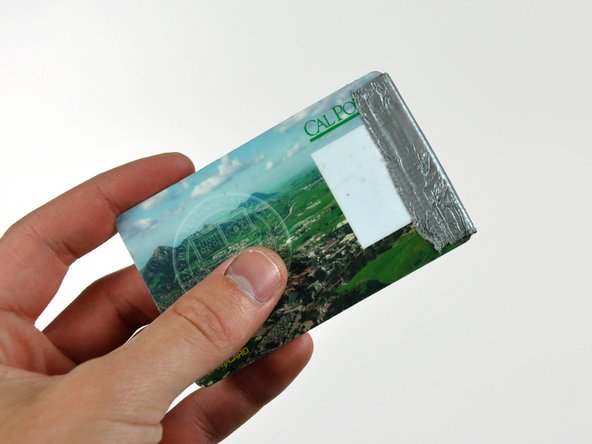
    • Peel back the aluminum EMI tape from the two vertical edges of the display.

    • During reassembly, it is helpful to use several small strips of tape to hold the EMI shielding along the left and right edges of the display footprint out of the way before lowering the display into the rear case of your iMac.

  12. この手順は未翻訳です。 翻訳を手伝う。

    : 手順 12、 2の画像 1 : 手順 12、 2の画像 2
    この手順で使用する道具:
    TR10 Torx Security Screwdriver
    $5.99
    購入する
    • Allow the EMI shield to hang down from the display.

    • Remove the four 8 mm with 2 mm thick head coarse-thread T10 Torx screws securing the display to the rear case.

    • These screws are recessed, so a thin screwdriver such as this is essential for removal. Bit drivers tend to be too short for this application.

    • It is strongly recommended to use a magnetized screwdriver so the screws won't fall into the iMac.

  13. この手順は未翻訳です。 翻訳を手伝う。

    : 手順 13、 1の画像 1
    • Lift the display from its lower edge and pull it toward yourself to peel off the EMI shield attached to its top edge.

    • Be mindful of any cables that may get caught during removal.

  14. : 手順 14、 1の画像 1
    • 左側スピーカーをリアケースに固定している30mm T10トルクスネジを外します。

  15. : 手順 15、 1の画像 1
    • 右側スピーカーから17mm T10トルクスネジを外します。

  16. この手順は未翻訳です。 翻訳を手伝う。

    : 手順 16、 1の画像 1
    この手順で使用する道具:
    Metal Spudger
    $2.99
    購入する
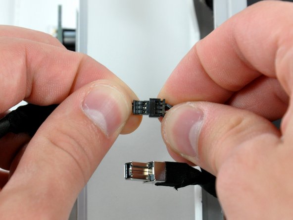
    • Pull the SATA data cable connector away from its socket on the logic board.

    • The SATA connector on most iMacs tends to stick in its socket on the logic board. If you are having trouble disconnecting the SATA cable, insert a metal spudger or any other thin tool into the gap between the SATA connector and its socket and twist the spudger's shaft to safely separate the two pieces.

  17. この手順は未翻訳です。 翻訳を手伝う。

    : 手順 17、 1の画像 1
    • Disconnect the CPU fan by pulling its connector up off the logic board.

  18. この手順は未翻訳です。 翻訳を手伝う。

    : 手順 18、 1の画像 1
    • Disconnect the hard drive power cable by pulling its connector up off the logic board.

  19. : 手順 19、 1の画像 1
    • スパッジャーの平面側先端を使って、AirPort ExtremeカードからAirPort Extremeアンテナコネクタを持ち上げます。

  20. : 手順 20、 1の画像 1
    • 必要であれば、左側スピーカーケーブルを覆っているテープを剥がします。

  21. この手順は未翻訳です。 翻訳を手伝う。

    : 手順 21、 2の画像 1 : 手順 21、 2の画像 2
    • Lift the left and right speakers out of the rear case.

    • The speaker cables are still attached to the logic board.

    • The right speaker cable may be routed under the power button cable or the CPU fan cable (or both). If so, disconnect both cables by pulling their connectors away from the face of the logic board.

  22. この手順は未翻訳です。 翻訳を手伝う。

    : 手順 22、 1の画像 1
    • Disconnect the speaker cable connector by pulling its connector away from the socket on the logic board.

    • Pull the connector parallel to the face of the logic board.

ゴール

ある他の人がこのガイドを完成しました。

以下の翻訳者の皆さんにお礼を申し上げます:

en jp

30%

railgunさんは世界中で修理する私たちを助けてくれています! あなたも貢献してみませんか?
翻訳を始める ›

作成者

3人の作成者と共同で作成されました。

Walter Galan

694,692 ポイント

1,203のガイドは作成済み

0 件のコメント

コメントを追加

統計データ:

過去 24時間: 0

過去 7 日: 4

過去 30 日: 14

今までの合計 6,889