メインコンテンツにスキップ

iDea USA CT702 Speaker Replacement

必要な工具と部品

  1. iDea USA CT702 Speaker  Replacement, Speaker: 手順 1、 3の画像 1 iDea USA CT702 Speaker  Replacement, Speaker: 手順 1、 3の画像 2 iDea USA CT702 Speaker  Replacement, Speaker: 手順 1、 3の画像 3
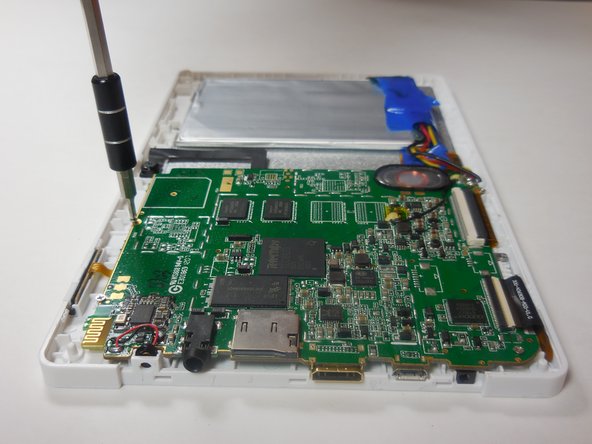
    • Place the tablet on a table with the portholes facing you.

    • Use fingernail or plastic opening tool to gently pry the black panel around the portholes.

    • Be gentle and take your time.

  2. iDea USA CT702 Speaker  Replacement: 手順 2、 1の画像 1
    • Use fingers to pry the rest of the back off; slowly apply pressure from each side to break each clip connection.

  3. iDea USA CT702 Speaker  Replacement: 手順 3、 3の画像 1 iDea USA CT702 Speaker  Replacement: 手順 3、 3の画像 2 iDea USA CT702 Speaker  Replacement: 手順 3、 3の画像 3
    • Once the back cover has been removed the device should look like this.

    • Remove the motherboard by unscrewing the four 4 mm screws along the edges of the board using a Philips 00 screwdriver.

  4. iDea USA CT702 Speaker  Replacement: 手順 4、 2の画像 1 iDea USA CT702 Speaker  Replacement: 手順 4、 2の画像 2
    • After removing the four screws, disconnect the two ribbon wires; to disconnect the wire lift up on on the plastic tab covering the wire.

    • When the tab is in the up position gently pull the ribbon wire out of its connection.

  5. iDea USA CT702 Speaker  Replacement: 手順 5、 1の画像 1
    • Once the ribbon wires are disconnected, gently lift up on the mother board and flip it.

    • All of the wires have not been disconnected from the motherboard. Be careful not to damage the remaining wires.

  6. iDea USA CT702 Speaker  Replacement: 手順 6、 3の画像 1 iDea USA CT702 Speaker  Replacement: 手順 6、 3の画像 2 iDea USA CT702 Speaker  Replacement: 手順 6、 3の画像 3
    この手順で使用する道具:
    Tweezers
    $4.99
    購入する
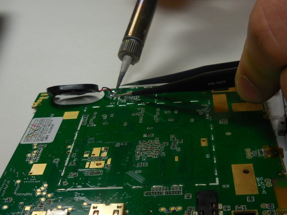
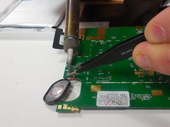
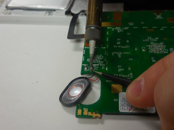
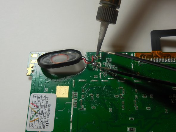
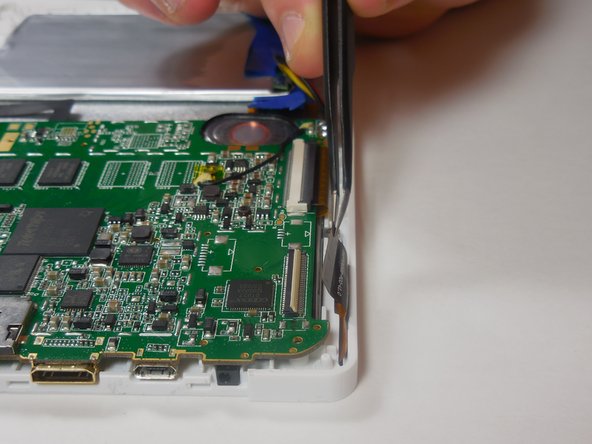
    • The speaker is located towards the edge of the motherboard. You will need to solder the speaker connections to remove it.

    • Your speaker may have a mesh cover and may not look like the one in the picture.

    • To solder the connections apart take the hot soldering iron and gently touch it to the end of the wire at the connection to the motherboard. At the same time use tweezers to gently pull the wire away from the connection.

  7. iDea USA CT702 Speaker  Replacement: 手順 7、 3の画像 1 iDea USA CT702 Speaker  Replacement: 手順 7、 3の画像 2 iDea USA CT702 Speaker  Replacement: 手順 7、 3の画像 3
    • To connect the new speaker you will need to solder the new wire connections onto the motherboard.

    • Gently touch the end of the new wire to the existing connection, and use the soldering iron to heat the solder and connect the wire.

    • You will need to do this for both of the speaker connections.

  8. iDea USA CT702 Speaker  Replacement: 手順 8、 3の画像 1 iDea USA CT702 Speaker  Replacement: 手順 8、 3の画像 2 iDea USA CT702 Speaker  Replacement: 手順 8、 3の画像 3
    • Once the new speaker is connected, gently lift the motherboard and place it back in the frame. Be sure to line up the holes to screw back in place.

    • Make sure the speaker is in its original place before screwing the device back together.

    • Use a Philips 00 screwdriver to screw in the four 4 mm screws along the edge of the motherboard.

  9. iDea USA CT702 Speaker  Replacement: 手順 9、 2の画像 1 iDea USA CT702 Speaker  Replacement: 手順 9、 2の画像 2
    • After screwing in the motherboard, reconnect the ribbon wires to their connections.

    • To do so, insert the ribbon wire into its slot and snap down the tabs on the wire's connection to secure them in place.

    • To replace the back cover follow the first three steps in reverse order

終わりに

To reassemble your device, follow these instructions in reverse order.

作成者

6人の作成者と共同で作成されました。

Daniel Brandt

メンバー登録日: 03/11/15

201 ポイント

2のガイドは作成済み

チーム

Colorado Springs, Team 4-7, Panko Spring 2015 Colorado Springs, Team 4-7, Panko Spring 2015人のメンバー

UCCS-PANKO-S15S4G7

3 メンバー

10のガイドは作成済み

0 件のコメント

コメントを追加

統計データ:

過去 24時間: 0

過去 7 日: 3

過去 30 日: 6

今までの合計 147