メインコンテンツにスキップ

このバージョンは誤った内容を含んでいる可能性があります。最新の承認済みスナップショットに切り替えてください。

必要な工具と部品

  1. この手順は未翻訳です。 翻訳を手伝う。

    : 手順 1、 2の画像 1 : 手順 1、 2の画像 2
    • Use a coin to rotate the battery locking screw 90 degrees clockwise.

    • Lift the battery out of the computer.

  2. この手順は未翻訳です。 翻訳を手伝う。

    : 手順 2、 1の画像 1
    • Pull the keyboard release tabs (shown in yellow) toward you and lift up on the keyboard until it pops free.

    • If the keyboard does not come free, use a small flathead screwdriver to turn the keyboard locking screw (shown in orange) 180 degrees in either direction and try again.

    • Flip the keyboard over, away from the screen, and rest it face-down on the trackpad area.

  3. この手順は未翻訳です。 翻訳を手伝う。

    : 手順 3、 1の画像 1
    • Loosen the four silver Phillips screws that secure the RAM shield.

    • These screws will not come out all the way. The screws are held captive to the RAM shield to prevent them from getting lost.

  4. この手順は未翻訳です。 翻訳を手伝う。

    : 手順 4、 1の画像 1
    • Remove the RAM shield from the computer.

    • The four captive screws will come out with the RAM shield.

  5. この手順は未翻訳です。 翻訳を手伝う。

    : 手順 5、 1の画像 1
    • Pull the keyboard cable up from the logic board, holding the cable as close to the connector as possible.

    • When reassembling your iBook, make sure that you reconnect the keyboard cable before replacing the RAM shield.

  6. この手順は未翻訳です。 翻訳を手伝う。

    : 手順 6、 1の画像 1
    • Close the display and flip the computer over.

    • Remove the three hex screws using a T8 Torx screwdriver.

    • The shorter screw is in the center.

  7. この手順は未翻訳です。 翻訳を手伝う。

    : 手順 7、 1の画像 1
    • Use a spudger or small flathead screwdriver to remove the three rubber feet from the lower case.

  8. この手順は未翻訳です。 翻訳を手伝う。

    : 手順 8、 1の画像 1
    • Remove the three newly-revealed Phillips screws.

    • One screw is underneath each bumper (three total).

  9. この手順は未翻訳です。 翻訳を手伝う。

    : 手順 9、 1の画像 1
    • Use a spudger or small flathead screwdriver to pry up the three metal rings that housed the rubber bumpers.

  10. この手順は未翻訳です。 翻訳を手伝う。

    : 手順 10、 1の画像 1
    • Remove the two Phillips screws on either side of the battery contacts.

  11. この手順は未翻訳です。 翻訳を手伝う。

    : 手順 11、 1の画像 1
    • Breathe deeply. Trying times are ahead, but we promise the lower case does come off.

    • Push in the thin rims of the lower case surrounding the battery compartment, bending them past the tabs, and then lift up to free that corner of the lower case.

  12. この手順は未翻訳です。 翻訳を手伝う。

    : 手順 12、 1の画像 1
    • There is a slot on the wall of the battery compartment that locks the lower case in place. Use a small flathead screwdriver to pry out the slot's lower rim and pull up on the lower case to free the slot from the tabs holding it.

  13. この手順は未翻訳です。 翻訳を手伝う。

    : 手順 13、 1の画像 1
    • Run a spudger along the seam between the lower case and upper case on the front of the computer to free the tabs locking the lower case. Pull up on the lower case and continue to use the spudger as necessary until you hear three distinct clicks.

  14. この手順は未翻訳です。 翻訳を手伝う。

    : 手順 14、 1の画像 1
    • Continue to run the spudger around the front, right corner. There are two tabs on the port side of the computer, one near the front corner and one near the sound-out port.

  15. この手順は未翻訳です。 翻訳を手伝う。

    : 手順 15、 1の画像 1
    • There are three tabs over the optical drive that must be released before the lower case can come off. Slide the spudger into the lower case above the optical drive and run it toward the back of the computer until you hear three distinct clicks.

  16. この手順は未翻訳です。 翻訳を手伝う。

    : 手順 16、 1の画像 1
    • The front and sides of the lower case are now free.

    • Turn the computer so that the back is facing you and pull the lower case up and toward you until the back tabs pop free.

    • It may be helpful to jiggle the case up and down.

  17. この手順は未翻訳です。 翻訳を手伝う。

    : 手順 17、 1の画像 1
    • Remove the small greasy springs with white plastic caps from either side of the battery contacts.

  18. この手順は未翻訳です。 翻訳を手伝う。

    : 手順 18、 1の画像 1
    • Remove the following 10 screws from the bottom shield:

    • Six 3 mm Phillips

    • Three 7.5 mm Phillips

    • One 14 mm Phillips

  19. この手順は未翻訳です。 翻訳を手伝う。

    : 手順 19、 1の画像 1
    • Lift the bottom shield off.

  20. この手順は未翻訳です。 翻訳を手伝う。

    : 手順 20、 1の画像 1
    • Remove the single Phillips screw securing the DC-In board.

  21. この手順は未翻訳です。 翻訳を手伝う。

    : 手順 21、 1の画像 1
    • Angle the DC-In board out of its compartment.

    • You may need to remove tape that secures the DC-In board cable to the case.

  22. この手順は未翻訳です。 翻訳を手伝う。

    : 手順 22、 1の画像 1
    • Lift the DC-In cable from the adhesive attaching it to the logic board.

  23. この手順は未翻訳です。 翻訳を手伝う。

    : 手順 23、 1の画像 1
    • Disconnect the DC-In cable from the logic board.

    • Wiggling the connector parallel to the surface of the logic board while applying slight tension may aid in removal.

  24. この手順は未翻訳です。 翻訳を手伝う。

    : 手順 24、 1の画像 1
    • Remove the following 11 screws from the bottom of the computer:

    • Three 3 mm Phillips around the battery compartment.

    • Three 4.5 mm Phillips along the optical drive bezel. (a magnetic screwdriver may help to lift these screws out)

    • One 12 mm Phillips in the lower right corner.

    • Four 14.5 mm Phillips.

  25. この手順は未翻訳です。 翻訳を手伝う。

    : 手順 25、 1の画像 1
    • We recommend placing the computer on a soft cloth from this point on to prevent damaging the logic board.

    • Turn over the computer and open it.

    • Remove the 3 Phillips screws from the edges of the keyboard area.

    • The shorter screw goes in the lower left corner. The left corner is indicated by a blue "L" in the photograph and is on the right side.

  26. この手順は未翻訳です。 翻訳を手伝う。

    : 手順 26、 1の画像 1
    • Be especially careful while disconnecting the cables in the forthcoming steps. Never pull directly on the cables, but use a spudger to pry up the connector directly from its socket.

    • Lift the upper case and use a spudger or your finger to disconnect the trackpad connector hidden beneath the white plastic tab.

    • Be careful while lifting the upper case, as its tabs are still hanging on the metal frame.

  27. この手順は未翻訳です。 翻訳を手伝う。

    : 手順 27、 1の画像 1
    • The sockets attached to the motherboards of most iBooks are very weak and easily broken. Use extreme caution when pulling connectors out of their sockets.

    • Lift the upper case enough to disconnect the blue and white power cable from the logic board. Using your fingernails, carefully pry the connector from its socket.

    • Carefully disconnect the multicolored speaker cable from the logic board in the same fashion.

  28. この手順は未翻訳です。 翻訳を手伝う。

    : 手順 28、 1の画像 1
    • Remove the following 16 screws:

    • Thirteen 3 mm Phillips.

    • One 3 mm Phillips.

    • Two 4 mm Phillips.

    • During reassembly, be sure to fit the screw near the left hinge through the loop in the display data cable, securing the cable to the upper case.

  29. この手順は未翻訳です。 翻訳を手伝う。

    : 手順 29、 1の画像 1
    • Lift the top shield up from the right side, minding the upper left corner which may catch on the metal framework.

  30. この手順は未翻訳です。 翻訳を手伝う。

    : 手順 30、 1の画像 1
    • Remove the two Phillips screws at the corners of the modem.

    • Remove the two Phillips screws at the corners of the modem.

  31. この手順は未翻訳です。 翻訳を手伝う。

    : 手順 31、 2の画像 1 : 手順 31、 2の画像 2
    • Use a spudger to pry the modem up from the end nearest the AirPort card to separate its connector from a socket on the logic board.

    • Be sure to pry only against the heat sink or the metal framework.

    • Use your hands to seperate the modem from the modem shield.

  32. この手順は未翻訳です。 翻訳を手伝う。

    : 手順 32、 1の画像 1
    • Disconnect the RJ-11 cable from the end of the modem.

    • When replacing the modem, first make sure that both the microphone and display data cables are routed beneath where the modem lies.

  33. この手順は未翻訳です。 翻訳を手伝う。

    : 手順 33、 1の画像 1
    • Remove the three 3 mm Phillips screws securing the AirPort card bracket to the framework.

    • Lift the AirPort card bracket up and out of the computer.

  34. この手順は未翻訳です。 翻訳を手伝う。

    : 手順 34、 1の画像 1
    • Remove the two 3 mm Phillips screws securing the AirPort card to the logic board.

  35. この手順は未翻訳です。 翻訳を手伝う。

    : 手順 35、 1の画像 1
    • Using a spudger, pry up on the AirPort card from the end nearest the hard drive to separate the connector from the logic board.

    • Be sure to pry only between the metal frame and the AirPort card.

  36. この手順は未翻訳です。 翻訳を手伝う。

    : 手順 36、 1の画像 1
    • Use a spudger to disconnect the two antenna cables from the AirPort card.

    • Remove the AirPort card from the computer and set it aside.

  37. この手順は未翻訳です。 翻訳を手伝う。

    : 手順 37、 1の画像 1
    • De-route the antenna wires from above the heat sink, around the RAM socket, and below the optical drive.

    • Optical drive removal is not necessary for this step.

  38. この手順は未翻訳です。 翻訳を手伝う。

    : 手順 38、 1の画像 1
    • Turn the computer over.

    • Disconnect the inverter cable from the logic board and deroute it from the metal framework, removing tape as necessary.

  39. この手順は未翻訳です。 翻訳を手伝う。

    : 手順 39、 1の画像 1
    • Turn the computer back over.

    • Use the black plastic loop to disconnect the display data cable from the logic board.

    • Deroute the microphone and display data cables from the metal framework, removing tape as necessary.

  40. この手順は未翻訳です。 翻訳を手伝う。

    : 手順 40、 1の画像 1
    • The cable you're about to remove is very fragile - do not pull directly on the wires. Instead, try to pry up the connector directly, using a spudger or a small flathead screwdriver if necessary.

    • Disconnect the microphone cable at the front of the computer, between the left side of the hard drive and the metal framework.

    • Deroute the microphone and display data cables from the metal framework, removing tape as necessary.

  41. この手順は未翻訳です。 翻訳を手伝う。

    : 手順 41、 1の画像 1
    • Support the display with one hand and remove the single Phillips screw on either side of the hinge (two screws total).

    • The screws go in the outer holes on each side (you can see the threads in the correct hole).

  42. この手順は未翻訳です。 翻訳を手伝う。

    : 手順 42、 1の画像 1
    • Lift the display up and tilt it backwards, freeing it from the two metal alignment posts holding the hinges in place, and slide it away from you.

    • Be sure all cables connecting the display to the computer are free before completely removing the display.

  43. この手順は未翻訳です。 翻訳を手伝う。

    : 手順 43、 1の画像 1
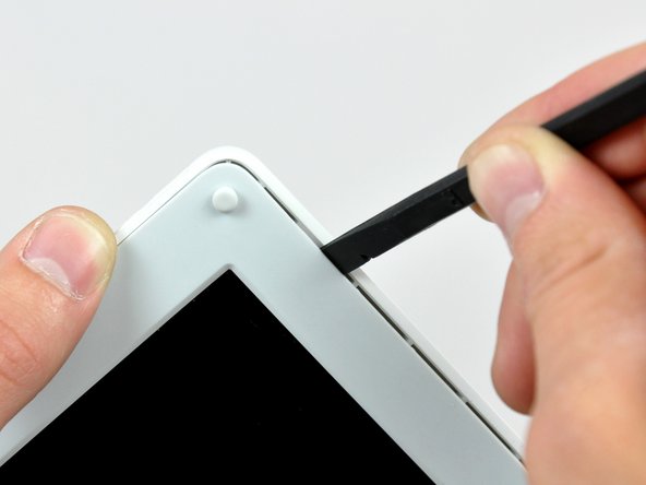
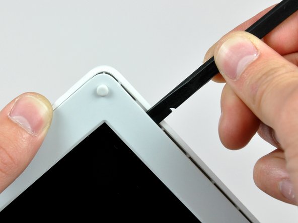
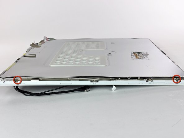
    • Use a 1.5 mm hex screwdriver to remove the two hex screws on either side of the display (four screws total).

    • If you don't have a 1.5 mm hex driver, you can probably get these screws out with a T6 Torx screwdriver. However, if you use a T6 Torx driver you'll be more likely to strip the screws.

  44. この手順は未翻訳です。 翻訳を手伝う。

    : 手順 44、 1の画像 1
    • Use your thumbs to slightly separate the rear bezel from the front bezel.

    • It is helpful to hold the opposing corner of the display stationary to aid in flexing the rear bezel away from the display.

  45. この手順は未翻訳です。 翻訳を手伝う。

    : 手順 45、 3の画像 1 : 手順 45、 3の画像 2 : 手順 45、 3の画像 3
    • Insert the flat end of a spudger into the gap between the front and rear bezels.

    • Rotate your spudger until it is parallel to the front face of the display.

    • Run the spudger around the perimeter of the display to separate the rear bezel from its retaining clips.

  46. : 手順 46、 1の画像 1
    • ディスプレイからリアベゼルを持ち上げます。

  47. この手順は未翻訳です。 翻訳を手伝う。

    : 手順 47、 2の画像 1 : 手順 47、 2の画像 2
    • Remove the pieces of readily removable tape from around the perimeter of the display.

    • Carefully remove the aluminum tape covering the display data cable connection.

  48. この手順は未翻訳です。 翻訳を手伝う。

    : 手順 48、 2の画像 1 : 手順 48、 2の画像 2
    • Remove the single screw inserted through the piece of EMI tape near the bottom edge of the display.

    • Use the tip of a spudger to remove the small washer under the screw you just removed.

  49. この手順は未翻訳です。 翻訳を手伝う。

    : 手順 49、 1の画像 1
    • Peel the aluminum/EMI tape off the cast aluminum frame of the clutch hinges.

    • It is not necessary to peel the tape off the thin steel LCD cover.

  50. この手順は未翻訳です。 翻訳を手伝う。

    : 手順 50、 2の画像 1 : 手順 50、 2の画像 2
    • Remove the two Phillips screws securing each side of the LCD to the clutch hinge frame (four screws total).

  51. この手順は未翻訳です。 翻訳を手伝う。

    : 手順 51、 1の画像 1
    • Lift the thin steel LCD cover off the LCD.

  52. この手順は未翻訳です。 翻訳を手伝う。

    : 手順 52、 1の画像 1
    • Remove the second of the two Phillips screws securing the clutch cover to the cast aluminum frame of the clutch hinges.

  53. この手順は未翻訳です。 翻訳を手伝う。

    : 手順 53、 3の画像 1 : 手順 53、 3の画像 2 : 手順 53、 3の画像 3
    • Pull the clutch cover away from the front of the display.

    • Keep track of the two covers that close the ends of the clutch cover. The third picture shows their correct orientation on the clutch cover.

  54. この手順は未翻訳です。 翻訳を手伝う。

    , ディスプレイデータケーブル: 手順 54、 1の画像 1
    • Remove the pieces of tape covering the display data and microphone cables near the bottom edge of the display.

  55. この手順は未翻訳です。 翻訳を手伝う。

    : 手順 55、 1の画像 1
    • Disconnect the display data cable by pulling its connector away from the socket on the LCD.

    • Pull the connector parallel to the face of the LCD.

    • Remove the display data cable from the display.

  56. この手順は未翻訳です。 翻訳を手伝う。

    : 手順 56、 2の画像 1 : 手順 56、 2の画像 2
    • Use the tip of a spudger to lift the microphone out of the front bezel.

    • De-route the microphone cable from around the top and side of the display.

  57. : 手順 57、 1の画像 1
    • ディスプレイからディスプレイデータケーブルを取り外します。

  58. この手順は未翻訳です。 翻訳を手伝う。

    , インバーター/AirPortケーブル: 手順 58、 2の画像 1 , インバーター/AirPortケーブル: 手順 58、 2の画像 2
    • Remove the two pieces of tape covering the inverter/AirPort cables along the lower edge of the display.

    • Carefully peel the inverter cable ground strap off the cast aluminum frame of the clutch hinges.

  59. この手順は未翻訳です。 翻訳を手伝う。

    : 手順 59、 2の画像 1 : 手順 59、 2の画像 2
    • Disconnect the backlight cable from the inverter.

    • It is helpful to use a spudger to push the backlight connector away from its socket while you lightly pull its cables away from the inverter.

  60. この手順は未翻訳です。 翻訳を手伝う。

    : 手順 60、 1の画像 1
    • Lift the LCD out of the display assembly.

    • It may be helpful to press the latch release button and open your display slightly to push the LCD out of the display assembly.

  61. この手順は未翻訳です。 翻訳を手伝う。

    : 手順 61、 1の画像 1
    • Remove the single Phillips screw securing the reed switch board to the front bezel.

    • Carefully lift the reed switch board off the metal frame of the clutch hinges.

  62. : 手順 62、 2の画像 1 : 手順 62、 2の画像 2
    • 右側AirPortアンテナをクラッチヒンジフレームに固定しているプラスネジを2本外します。

    • クラッチヒンジフレームから右側AirPortアンテナを注意深く持ち上げます。

  63. : 手順 63、 2の画像 1 : 手順 63、 2の画像 2
    • 左側AirPortアンテナをクラッチヒンジフレームに固定しているプラスネジを2本外します。

    • クラッチヒンジフレームから左側AirPortアンテナを注意深く持ち上げます。

  64. : 手順 64、 1の画像 1
    • スパッジャーの平面側を使って、フロントベゼルからアンテナボードを取り外します。

    • アンテナボードは、とても薄く、脆いです。

  65. この手順は未翻訳です。 翻訳を手伝う。

    : 手順 65、 2の画像 1 : 手順 65、 2の画像 2
    • Remove the single Phillips screw securing the front bezel to the middle of the cast aluminum clutch hinge frame.

    • Carefully bend the front display bezel away from the clutch hinges as you slide the two AirPort antennas out from under the clutch hinge frame.

  66. この手順は未翻訳です。 翻訳を手伝う。

    : 手順 66、 2の画像 1 : 手順 66、 2の画像 2
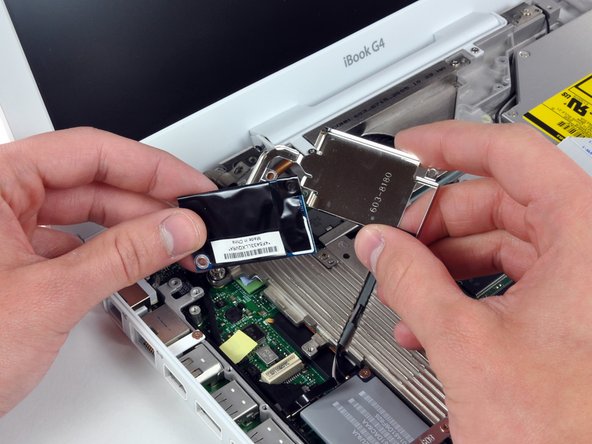
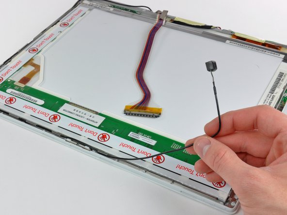
    • While pulling the inverter cable away from its socket on the inverter board, use the tip of a spudger to push the connector out of its socket.

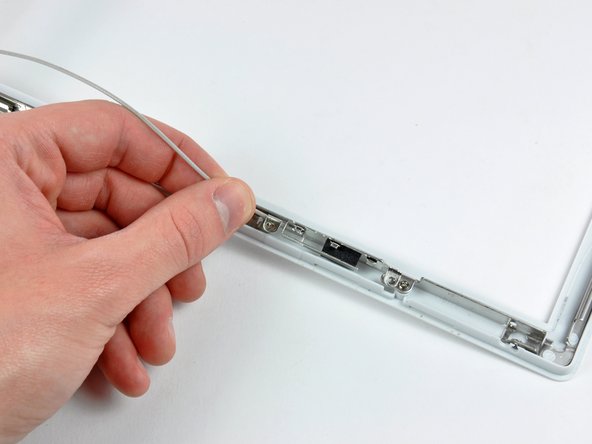
    • If the connector won't budge from its socket, insert a metal spudger or similar tool into the gap between the connector and its socket and twist to separate the two pieces.

  67. , クラッチヒンジ: 手順 67、 2の画像 1 , クラッチヒンジ: 手順 67、 2の画像 2
    • クラッチヒンジをフロントディスプレイベゼルに固定しているプラスネジを6本外します。

    • フロントディスプレイベゼルからクラッチヒンジを持ち上げます。

ゴール

ある他の人がこのガイドを完成しました。

作成者

2人の作成者と共同で作成されました。

Andrew Bookholt

586,109 ポイント

619のガイドは作成済み

0 件のコメント

コメントを追加

統計データ:

過去 24時間: 0

過去 7 日: 0

過去 30 日: 2

今までの合計 3,458