メインコンテンツにスキップ

このバージョンは誤った内容を含んでいる可能性があります。最新の承認済みスナップショットに切り替えてください。

必要な工具と部品

  1. この手順は未翻訳です。 翻訳を手伝う。

    : 手順 1、 1の画像 1
    • Use a coin to rotate the battery locking screw 90 degrees clockwise.

    • Lift the battery out of the computer.

  2. この手順は未翻訳です。 翻訳を手伝う。

    : 手順 2、 2の画像 1 : 手順 2、 2の画像 2
    • Use a 1.5 mm hex screwdriver to remove the two hex screws on either side of the display (four screws total).

    • If you don't have a 1.5 mm hex driver, you can probably get these screws out with a T6 Torx screwdriver. However, if you use a T6 Torx driver you'll be more likely to strip the screws.

  3. この手順は未翻訳です。 翻訳を手伝う。

    : 手順 3、 2の画像 1 : 手順 3、 2の画像 2
    • Insert the flat end of a spudger perpendicular to the face of the display into the gap between the front and rear bezels near the upper left corner of the display.

    • Rotate the spudger away from the display to pry the rear bezel off the front bezel.

  4. この手順は未翻訳です。 翻訳を手伝う。

    : 手順 4、 1の画像 1
    • Run your spudger along the top edge of the front display bezel to evenly separate the two bezels.

  5. この手順は未翻訳です。 翻訳を手伝う。

    : 手順 5、 2の画像 1 : 手順 5、 2の画像 2
    • Working down from the upper left corner, use the flat end of a spudger to pry the rear bezel away from the left edge of the display.

  6. この手順は未翻訳です。 翻訳を手伝う。

    : 手順 6、 1の画像 1
    • Use the flat end of a spudger to pry the rear bezel away from the right edge of the display.

    • If necessary, pry along the bottom edge of the rear bezel to separate it from the display assembly.

  7. この手順は未翻訳です。 翻訳を手伝う。

    : 手順 7、 1の画像 1
    • Lift the rear bezel off the display assembly.

  8. この手順は未翻訳です。 翻訳を手伝う。

    : 手順 8、 2の画像 1 : 手順 8、 2の画像 2
    • Close the display.

    • Remove the several pieces of tape securing the thin metal LCD cover to the display.

    • Carefully remove the piece of foil tape covering the display data cable connection.

  9. この手順は未翻訳です。 翻訳を手伝う。

    : 手順 9、 2の画像 1 : 手順 9、 2の画像 2
    • Remove the Phillips screw near the right display hinge.

    • Use the tip of a spudger to remove the small spacer under the screw you just removed.

  10. この手順は未翻訳です。 翻訳を手伝う。

    : 手順 10、 1の画像 1
    • Pull the foil/braided pieces of tape off the aluminum frame of the clutch hinges.

    • Leave the tape attached to the thin steel LCD cover.

  11. この手順は未翻訳です。 翻訳を手伝う。

    : 手順 11、 2の画像 1 : 手順 11、 2の画像 2
    • Remove the two Phillips screws securing the left and right sides of the LCD to the frame of the clutch hinges (four screws total).

  12. この手順は未翻訳です。 翻訳を手伝う。

    : 手順 12、 1の画像 1
    • Carefully remove the thin steel LCD cover.

  13. この手順は未翻訳です。 翻訳を手伝う。

    : 手順 13、 1の画像 1
    • Disconnect the display data cable by pulling the cable away from the socket on the LCD.

  14. この手順は未翻訳です。 翻訳を手伝う。

    : 手順 14、 1の画像 1
    • Remove the strip of yellow tape securing the display data cable to the metal LCD frame.

  15. この手順は未翻訳です。 翻訳を手伝う。

    : 手順 15、 2の画像 1 : 手順 15、 2の画像 2
    • Disconnect the backlight cable from the inverter.

    • It is helpful to use a spudger to push the backlight connector away from its socket while you lightly pull its cables away from the inverter.

  16. この手順は未翻訳です。 翻訳を手伝う。

    : 手順 16、 1の画像 1
    • Lift the LCD out of the display assembly.

    • It may be helpful to press the latch release button and open your display slightly to push the LCD out of the display assembly.

  17. この手順は未翻訳です。 翻訳を手伝う。

    : 手順 17、 1の画像 1
    • Remove the two pieces of yellow tape covering the inverter/AirPort cables.

  18. この手順は未翻訳です。 翻訳を手伝う。

    : 手順 18、 1の画像 1
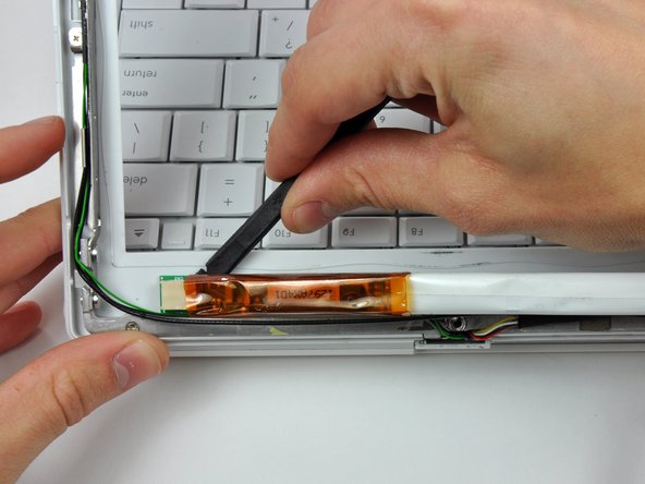
    • Disconnect the inverter cable by pulling its connector away from the socket on the inverter board.

    • The inverter board is a very thin and delicate circuit board that is easily broken. Use caution.

    • This connector tends to stick in its socket. It is helpful to push the connector with the tip of a spudger through the two small holes in the top of the socket while pulling the connector away from the socket.

    • Make sure to grasp the inverter cabling by the black tape and not the individual wires. Pulling the wires themselves will surely damage the inverter cable.

  19. この手順は未翻訳です。 翻訳を手伝う。

    : 手順 19、 2の画像 1 : 手順 19、 2の画像 2
    • Insert the flat end of a spudger under the middle of the inverter board.

    • Slide the spudger to the far left and right edges to separate the inverter board from the adhesive securing it to the front bezel.

    • Remove the inverter board.

ゴール

作成者

2人の作成者と共同で作成されました。

Andrew Bookholt

586,305 ポイント

619のガイドは作成済み

0 件のコメント

コメントを追加

統計データ:

過去 24時間: 0

過去 7 日: 0

過去 30 日: 2

今までの合計 2,201