Pull the keyboard release tabs (highlighted in red) toward you and lift up on the keyboard until it pops free.
If the keyboard does not come free, use a small flathead screwdriver to turn the keyboard locking screw 180 degrees in either direction and try again.
Flip the keyboard over, away from the screen, and rest it face-down on the trackpad area.
If your computer does not have an AirPort card installed, skip to the RAM shield removal step.
Push the wire clasp toward the AirPort card and pull it up to free it from the RAM shield.
Breathe deeply. Trying times are ahead, but we promise the lower case does come off.
Push the thin rims of the lower case surrounding the battery compartment in, bending them past the tabs, and then lift up to free that corner of the lower case.
There is a slot on the wall of the battery compartment that locks the lower case in place.
Use a small flathead screwdriver to pry out the slot's lower rim and pull up on the lower case to free the slot from the tabs holding it.
Run a spudger along the seam between the lower case and upper case on the front of the computer to free the tabs locking the lower case.
Pull up on the lower case and continue to use the spudger as necessary until you hear three distinct clicks.
Continue to run the spudger around the front, right corner.
There are two tabs on the port side of the computer, one near the front corner and one near the sound out port.
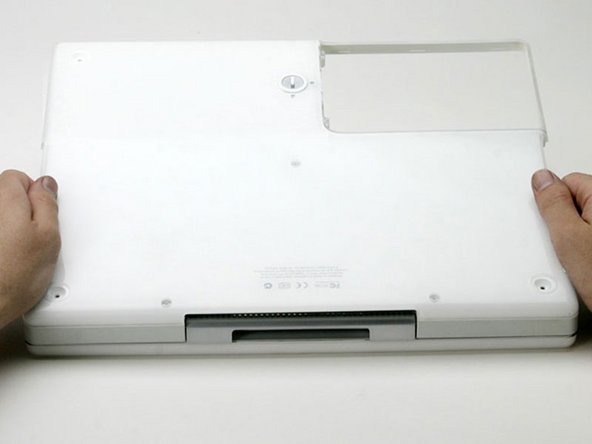
Once the front and sides of the lower case are free, turn the computer so that the back is facing you.
Pull the lower case up and toward you until the back tabs pop free.
It may be helpful to jiggle the case up and down.
All of the screws in the following step have small heads - the screws with larger heads hold the bottom shield on.
Remove the following 9 screws on the bottom of the computer:
Three 3 mm Phillips around the battery compartment.
Three 5 mm Phillips on the left and bottom edges.
Three 14.5 mm Phillips on the top and right edges (you may have to peel back the foil tape to reveal the screw near the security lock slot).
Turn over the computer and open it.
Pry up the magnet covering a Phillips screw near the middle of the computer.
You may need to peel back the serial number sticker to access the magnet.
Remove the following 3 screws on the edges of the keyboard area:
Two 6 mm Phillips underneath the keyboard area.
One 9 mm Phillips above the keyboard area.
On some models, there may also be a screw under the magnet you just removed. If so, remove the screw at this point.
This is a diagram of the ribbon clamp connectors you will disconnect in the next step.
With your fingernails, grasp the locking bar on either side and pull up a small amount (about 1/16" or 2 mm).
After disengaging the locking bar, slide the cable out of the connector.
Loosen the trackpad connector by pulling the top piece up slightly, freeing the trackpad ribbon.
Slide the orange trackpad ribbon out of the connector.
Don't lift the upper case off the computer yet as there are still two cables left to disconnect.
Lift the upper case from the left side and use your other hand to pull out the right side in order to clear the power receptacle.
The connectors at the ends of the cables are attached very firmly to the sockets on the logic board. Pulling directly on the cable will either separate the cable from its connector or the socket from the logic board.
Lift the upper case enough to disconnect the blue and white power cable from the logic board.
Using your fingernails or a dental pick, carefully pry the connector from its socket.
Make sure you are pulling only on the connector and not on the socket.
If you have already removed the yellow tape, skip this step.
Peel back three strips of yellow tape in the bottom, left corner.
Peel back one strip of foil tape near the audio-out port, one near where the trackpad connects to the logic board, and one near where the screen latch used to be.
If you have already removed the hard drive, ignore its presence in the following steps. The hard drive does not affect the display removal.
Disconnect the microphone cable from the front, left corner of the logic board.
Peel back the black tape and free the microphone cable from the hard drive.
If you have already removed the modem, you will only need to remove one of these screws.
Remove the two Phillips screws securing the display data cable to the metal framework.
Support the display with your free hand removing the following screws.
Remove the single Phillips screw on the outer edge of either hinge (two screws total).
Tilt the display back to get over two small nubbins, and then slide it directly from the case and away.
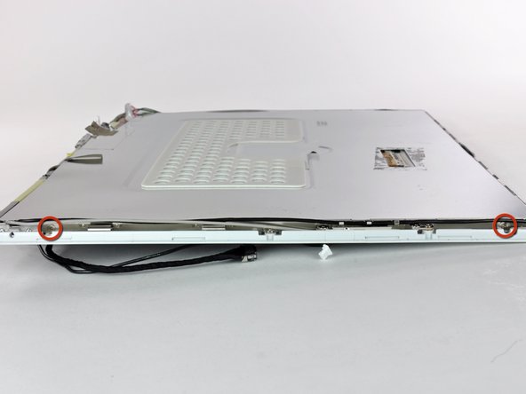
Use a 1.5 mm hex screwdriver to remove the two hex screws on either side of the display (four screws total).
If you don't have a 1.5 mm hex driver, you can probably get these screws out with a T6 Torx screwdriver. However, if you use a T6 Torx driver you'll be more likely to strip the screws.
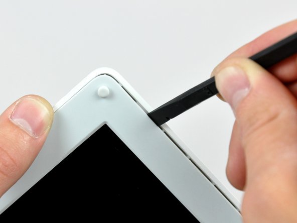
Insert the flat end of a spudger into the gap between the front and rear bezels.
Rotate your spudger until it is parallel to the front face of the display.
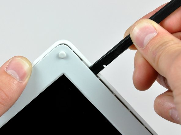
Run the spudger around the perimeter of the display to separate the rear bezel from its retaining clips.
このガイドを埋め込む
サイズを選択し、以下のコードをコピーして、このガイドを小さなウィジェットとしてサイト/フォーラムに埋め込みます。
1つの手順
全ガイド
小サイズ - 600px
中サイズ - 800px
大サイズ - 1200px
プレビュー