はじめに
Battery replacement for the "AK1" rocker switch from Amazon's Zoiinet smart switch eco-system
必要な工具と部品
-
-
Dislodge the switch mounting plate from the wall (if applicable -- you may have adhesive on the back or basic screws)
-
-
-
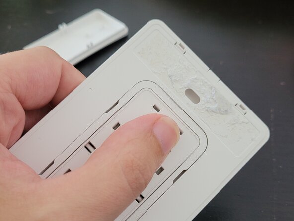
Gently press on the rocker switch from the back of the plate, it should easily pop out.
-
-
-
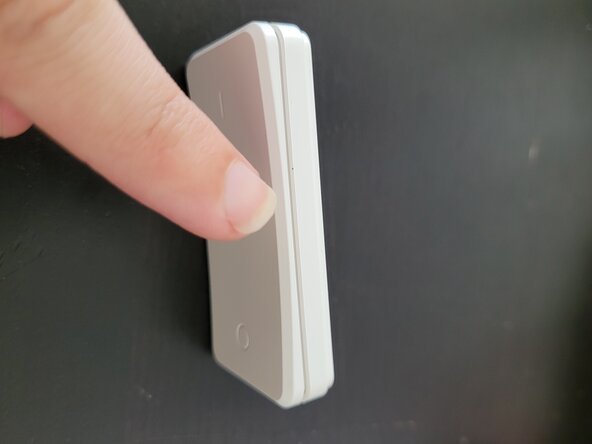
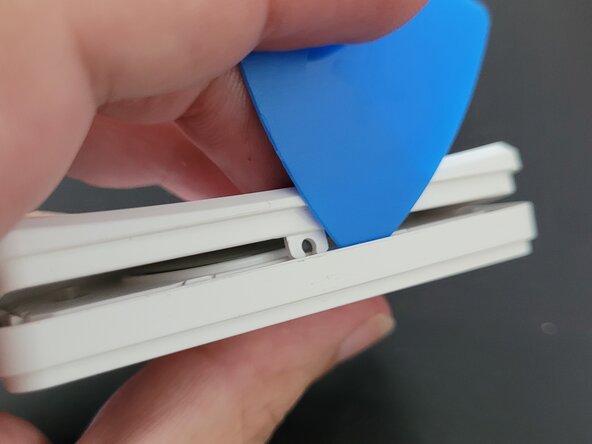
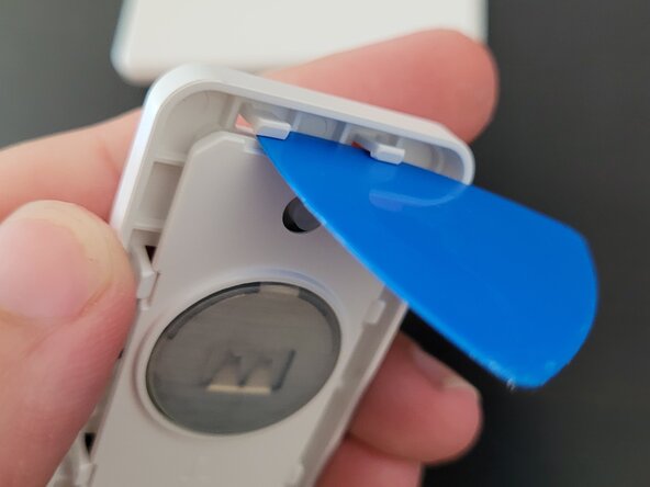
Using either an iFixit pick or fingernail gently pull apart from the middle of the switch on one side. The switch face should pop off its hinge.
-
-
-
-
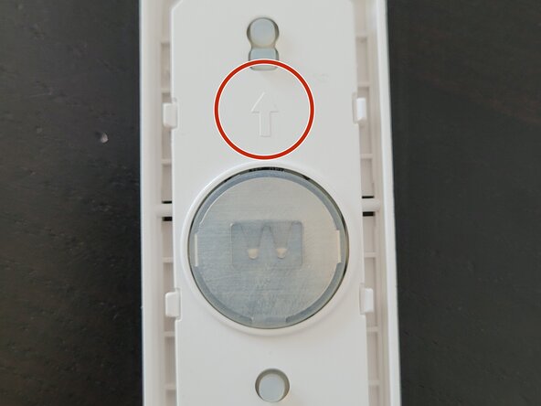
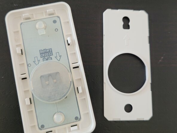
There is an inner plastic plate held in place by 8x plastic tabs (2 on each side). Inset the iFixit pick into each pair, gently wedging/rotating in until the tabs are blocked for 2 or 3 sides. The inner plate should come loose
-
Note: There is an up arrow indicating the "on" portion of the switch. This matches an arrow on the back of the rocker switch from the previous step
-
-
-
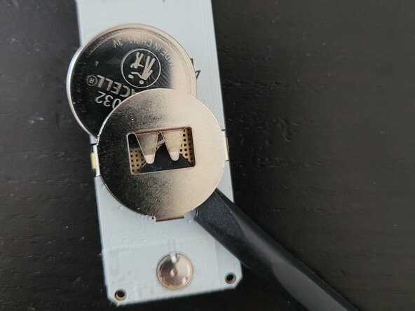
The silicon membrane sits loosely atop the circuit board and the CR2032 battery within. Lift both out.
-
-
-
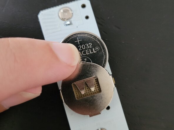
Use a small screwdriver, pen, or iFixit opener tool and press from the underside of the battery compartment to slide the old battery up and out.
-
Insert a new CR2032 battery from the top, the positive (+) side should face you
-
-
-
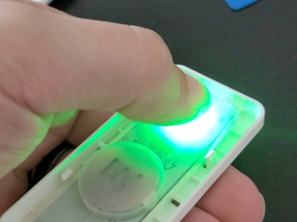
Restore the circuit board and membrane to the inner housing. If all is functional, the On button at the top (up arrow) should flash a green LED when the circuit connects.
-


To reassemble your device, follow these instructions in reverse order.
You're done! Congratulations!