メインコンテンツにスキップ

このバージョンは誤った内容を含んでいる可能性があります。最新の承認済みスナップショットに切り替えてください。

必要な工具と部品

  1. この手順は未翻訳です。 翻訳を手伝う。

    : 手順 1、 2の画像 1 : 手順 1、 2の画像 2
    • Carefully slide the heavy duty opening tool between the gap on the side of the device with no buttons.

    • Do not insert the opening tool too far into the tablet as this can damage connectors close to edges of the cover.

    • The angled tip of the opening tool can be wedged into the device by pressing on the back of the opening tool with the thumb. Move the opening tool in a sliding motion to ensure all tabs separate.

    • Corner tabs may require a more forceful prying tool. If needed, carefully insert the metal prying tool into corners to separate the tabs.

  2. この手順は未翻訳です。 翻訳を手伝う。

    : 手順 2、 1の画像 1
    • Look into the tablet for loose connectors.

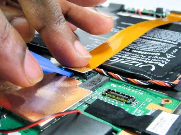
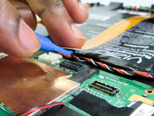
    • There are three loose connectors: one for the screen, one for the digitizer, and one for the motherboard. They are held in place by the pressure of the backing and screen assemblies.

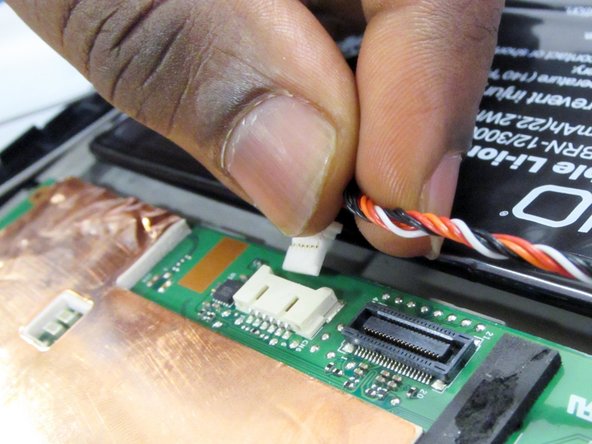
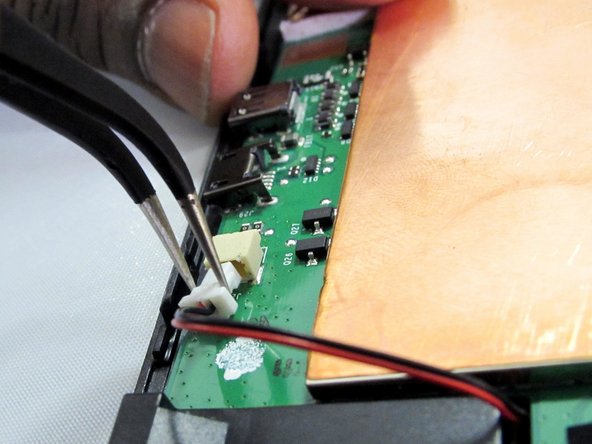
    • Flip the backing from the button-less side over, being careful not to separate the ribbon connector from the display screen.

  3. この手順は未翻訳です。 翻訳を手伝う。

    : 手順 3、 3の画像 1 : 手順 3、 3の画像 2 : 手順 3、 3の画像 3
    • Remove the motherboard by unscrewing the four securing screws with a J1 Phillip's head screwdriver.

    • 3 of the screws are clearly visible while the 4th is hidden by black tape on the upper left corner of the motherboard.

  4. この手順は未翻訳です。 翻訳を手伝う。

    : 手順 4、 3の画像 1 : 手順 4、 3の画像 2 : 手順 4、 3の画像 3
    この手順で使用する道具:
    Tweezers
    $4.99
    購入する
    • Remove both antenna connectors with a blue opening tool/tweezers.

  5. この手順は未翻訳です。 翻訳を手伝う。

    : 手順 5、 3の画像 1 : 手順 5、 3の画像 2 : 手順 5、 3の画像 3
    • Remove the ribbon connector at the top of the motherboard using the opening tool.

  6. この手順は未翻訳です。 翻訳を手伝う。

    : 手順 6、 2の画像 1 : 手順 6、 2の画像 2
    • Remove the connector at the top of the motherboard by pulling the connector away from the motherboard with fingers or tweezers.

  7. この手順は未翻訳です。 翻訳を手伝う。

    : 手順 7、 3の画像 1 : 手順 7、 3の画像 2 : 手順 7、 3の画像 3
    • Remove the connector at the side of the motherboard using the opening tool.

    • The connector is covered by a piece of black tape.

  8. この手順は未翻訳です。 翻訳を手伝う。

    : 手順 8、 2の画像 1 : 手順 8、 2の画像 2
    • Remove the red and black wire connector from the motherboard using either fingers or tweezers.

  9. この手順は未翻訳です。 翻訳を手伝う。

    : 手順 9、 3の画像 1 : 手順 9、 3の画像 2 : 手順 9、 3の画像 3
    • Flip the motherboard over.

    • Directly underneath the USB Charging connector will be four solder points that need to be undone in order to remove the charging port.

ゴール

ある他の人がこのガイドを完成しました。

作成者

5人の作成者と共同で作成されました。

Gilberto Ambriz

メンバー登録日: 09/29/16

546 ポイント

5のガイドは作成済み

チーム

Eastern Washington University, Team 1-1, Crane Fall 2016 Eastern Washington University, Team 1-1, Crane Fall 2016人のメンバー

EWU-CRANE-F16S1G1

4 メンバー

12のガイドは作成済み

0 件のコメント

コメントを追加

統計データ:

過去 24時間: 0

過去 7 日: 1

過去 30 日: 10

今までの合計 1,242