メインコンテンツにスキップ

Vivitar DVR 781HD Screen Replacement

必要な工具と部品

  1. Vivitar DVR 781HD Screen Replacement, Front Case: 手順 1、 3の画像 1 Vivitar DVR 781HD Screen Replacement, Front Case: 手順 1、 3の画像 2 Vivitar DVR 781HD Screen Replacement, Front Case: 手順 1、 3の画像 3
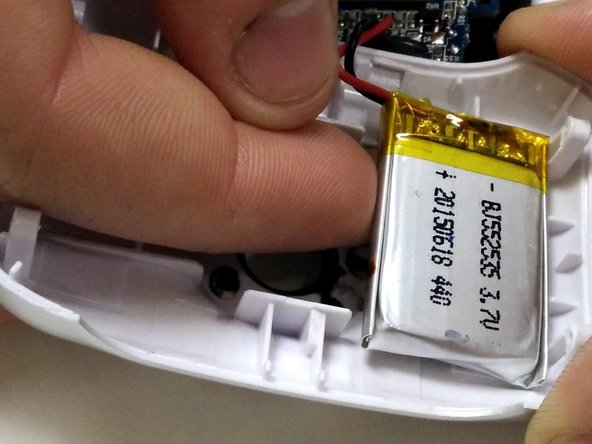
    • Begin with the camcorder lens up on a clear working surface.

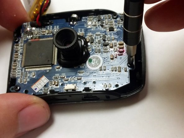
    • Remove the two 4mm Phillips #1 screws holding the switch plate in place. Rotate the device 180 degrees and repeat for the screws on the opposite side.

  2. Vivitar DVR 781HD Screen Replacement: 手順 2、 1の画像 1
    • Slide the plastic opening tool into the seam between the front and back sections of the case and apply a small amount of force to pop the case open.

  3. Vivitar DVR 781HD Screen Replacement: 手順 3、 3の画像 1 Vivitar DVR 781HD Screen Replacement: 手順 3、 3の画像 2 Vivitar DVR 781HD Screen Replacement: 手順 3、 3の画像 3
    • Move the plastic opening tool around the seam and apply force at each step to separate the front plate from the back plate and motherboard.

    • The battery is held to the front half of the case with double-sided tape. Peel it up with a finger, being careful not to damage the battery.

  4. Vivitar DVR 781HD Screen Replacement, Motherboard: 手順 4、 2の画像 1 Vivitar DVR 781HD Screen Replacement, Motherboard: 手順 4、 2の画像 2
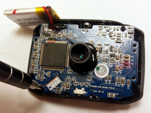
    • Using a P1 screwdriver, remove the 4mm screws holding the motherboard into the case.

  5. Vivitar DVR 781HD Screen Replacement: 手順 5、 1の画像 1
    • Gently lift the motherboard, handling it by the edges.

  6. Vivitar DVR 781HD Screen Replacement, Screen: 手順 6、 2の画像 1 Vivitar DVR 781HD Screen Replacement, Screen: 手順 6、 2の画像 2
    • Remove the two 4mm Phillips #1 screws holding the screen assembly to the motherboard.

  7. Vivitar DVR 781HD Screen Replacement: 手順 7、 2の画像 1 Vivitar DVR 781HD Screen Replacement: 手順 7、 2の画像 2
    • Turn the motherboard and screen over.

    • Gently lift the screen from the motherboard, handling it by the edges of the black plastic holder.

  8. Vivitar DVR 781HD Screen Replacement: 手順 8、 1の画像 1
    • Using a soldering iron, melt the solder connection between the screen's ribbon cable and the motherboard. Pull the ribbon cable away before the solder solidifies.

終わりに

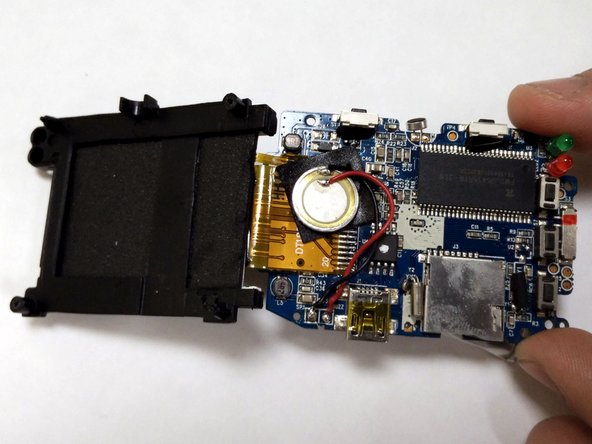
To reassemble your device, follow these instructions in reverse order.

2 の人々がこのガイドを完成させました。

作成者

2人の作成者と共同で作成されました。

Nathan McDaniel

メンバー登録日: 02/13/16

592 ポイント

3のガイドは作成済み

チーム

IUPUI, Team 54-6, Wilson Spring 2016 IUPUI, Team 54-6, Wilson Spring 2016人のメンバー

IUPUI-WILSON-S16S54G6

3 メンバー

10のガイドは作成済み

0 件のコメント

コメントを追加

統計データ:

過去 24時間: 0

過去 7 日: 0

過去 30 日: 3

今までの合計 574