はじめに
This guide provides detailed steps on replacing your device’s interface board. The interface board is your connection between your device keypad and main board. You will first need to disassemble the front and rear enclosure of your device in order to access the interface board. Once exposed, you will then be able to use this replacement guide. Replacing your interface board is usually the last solution you will come to if you are experiencing problems with display errors and controls. In order to replace the interface board, you will need to purchase a replacement part, and obtain a Phillips Head screwdriver. This replacement is moderately difficult, and may take around an hour.
For more information on replacing the interface board, please refer to page 142 in the service manual.
必要な工具と部品
-
手順1 Tools and equipment
注意: 手順 1-9 は、作業進行中としてマークされている ガイド から引用されています。
-
Screwdriver, Phillips, #1
-
Hex Key, 3mm, 9 inch length
-
Nutdriver, 7mm
-
Pliers, needle-nosed
-
-
-
Place the ventilator, face down, on an appropriate protective surface. (The foam inserts from the original iVent201 shipping carton are well suited for this purpose).
-
Detach the roll stand adapter plate from the bottom of the unit by removing the (4) 3mm x 8mm Phillips head screws and lock washers.
-
-
-
Use the hex key to remove the (2) 4mm x 30mm screws and washers from the bottom-rear of the enclosure
-
Lift the ventilator carrying handle and use the hex key to remove the (2) 4mm x 50mm screws and washers from the top-rear of the enclosure
-
-
-
Stand the unit back to an upright position and pull the front enclosure apart from the rear enclosure approximately 4 inches.
-
-
-
Disconnect the three tubes from the barbed fittings along the bottom of the inside of the front enclosure. Be sure to note where they were connected.
-
-
-
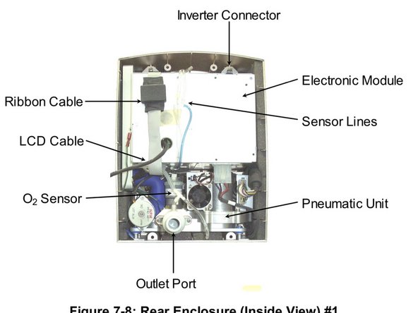
Disconnect the ribbon cable from the interface PC board located in the middle of the front enclosure.
-
Disconnect the green ground wire and receptacle from the pneumatic unit (just above the outlet port).
-
Disconnect the inverter cable from the top of the electronic module.
-
With the LCD cable still tethered, lay the front enclosure, face down, on the protective surface.
-
It is best to orient the front enclosure so that it is facing you, upside down with the tethered LCD cable towards the right
-
Detach the green LCD cable ground wire from the LCD shield by removing the (1) 3mm x 14mm Phillips head screw and lock washer located in the corner near the LCD connector.
-
Use the nutdriver to remove the (2) 4mm lock nuts from the LCD connector location on the front enclosure. Remove the aluminum U-shaped bracket from the LCD connector site and pull out the LCD connector and cable.
-
Remove the aluminum U-shaped bracket from the LCD connector site and pull out the LCD connector and cable.
-
-
-
Position the front enclosure face down on a protective surface so that it is upside down and to the left of the rear enclosure assembly.
-
Plug in LCD connector/ cable into the connector located through the LCD shield.
-
Install the U-shaped aluminum bracket oriented foam side down onto the studs protruding from the LCD shield.
-
Thread the (2) 4mm lock nuts onto the studs. While pressing down on the center of the bracket, tighten both lock nuts.
-
Attach the green LCD ground wire to the corner of the LCD shield with the (1) 3mm x 14mm Phillips head screw and lock washer.
-
Position the front enclosure standing up so that it is approximately 4 inches from the rear enclosure.
-
Connect the inverter cable to the top of the electronic module.
-
Connect the ribbon cable (from the bottom of the electronic module) to the interface PC board located in the middle of the front enclosure. Verify that the connector's side retaining clips are snapped into place.
-
-
-
Connect the ground cable to the spade terminal located just above the outlet port.
-
Connect the three (3) tubes to the barbed fittings located along the bottom of the inside of the front enclosure. Be sure to reconnect them to the same locations that they were removed from:
-
The tube from the outlet port tee is connected to the left-most fitting (when viewed from the inside).
-
The blue tube (or tube with a blue stripe) is connected to the right- most fitting.
-
The remaining tube is connected to the last remaining fitting
-
Bring the front and rear enclosures together. Orient the tubing and cables so that none are kinked or crimped.
-
Place the unit, face down, on the protective surface.
-
-
-
Under the weight of the rear enclosure (and assembly), the seam around the entire perimeter of the unit should be closed and even. If it is not, then there is interference from the tubes and/or cables that were just connected.
-
Install the (2) 4mm x 30mm screws and lock washers to the bottom-rear of the enclosure.
-
Install the (2) 4mm x 50mm screws and lock washers to the top-rear of the enclosure.
-
Attach the roll stand adapter plate to the bottom of the unit by installing the (4) 3mm x 8mm Phillips head screws and lock washers. Be sure to orient the plate so that the single middle hole is toward the rear of the unit.
-
-
-
Remove the two 3x8 mm screws and 4mm washers at the two ends of the PC Board with a Phillips Head screwdriver.
-
-
-
FOLLOW THESE STEPS IF THERE IS A SPEAKER PRESENT.
-
Disconnect the 6 pin encoder connector from the interface board by pulling upwards in the direction of the cable. This connector will be blue and circular.
-
Disconnect the 2 pin speaker connector from the interface board. This connector will be white and rectangular.
-
Set the front enclosure flat in front of you. Slide the interface board up vertically to remove it.
-
-
-
FOLLOW THESE STEPS IF THERE IS NO SPEAKER PRESENT.
-
Use a flat head screwdriver to remove the rotating control knob from the encoder shaft
-
Remove the mounting threads on the outside of the encoder shaft with a 11 mm nut driver. Make sure to remove all nuts and lock washers from these mounting holes.
-
Place the front enclosure on a flat surface, and orient the front to be facing down. Maintaining this position, remove the encoder shaft out of the mounting hole.
-
Flip the front enclosure and place it flat in front of you. Slide the interface board up vertically to remove it.
-


To reassemble your device, follow these instructions in reverse order.
To reassemble your device, follow these instructions in reverse order.
チーム

Cal Poly, Team 2-1, Johann Winter 2023 Cal Poly, Team 2-1, Johann Winter 2023人のメンバー
CPSU-JOHANN-W23S2G1
4 メンバー
5のガイドは作成済み