メインコンテンツにスキップ

Stove Element Receptacle Replacement

必要な工具と部品

  1. Stove Element Receptacle Replacement, Stove Element Receptacle: 手順 1、 3の画像 1 Stove Element Receptacle Replacement, Stove Element Receptacle: 手順 1、 3の画像 2 Stove Element Receptacle Replacement, Stove Element Receptacle: 手順 1、 3の画像 3
    • First, locate the the gas safety shut-off valve and turn off the power supply.

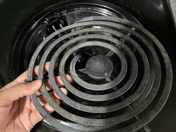
    • Remove the pitted scorched burner.

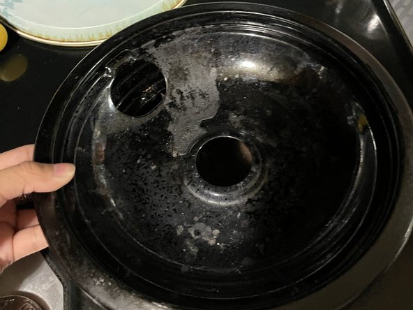
    • Remove the drip tray after removing the pitted scorched burner.

  2. Stove Element Receptacle Replacement: 手順 2、 3の画像 1 Stove Element Receptacle Replacement: 手順 2、 3の画像 2 Stove Element Receptacle Replacement: 手順 2、 3の画像 3
    • Look for the receptacle mounting screw and loosen it with a screwdriver.

  3. Stove Element Receptacle Replacement: 手順 3、 3の画像 1 Stove Element Receptacle Replacement: 手順 3、 3の画像 2 Stove Element Receptacle Replacement: 手順 3、 3の画像 3
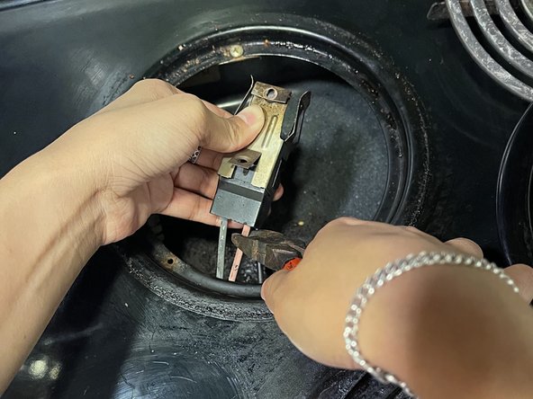
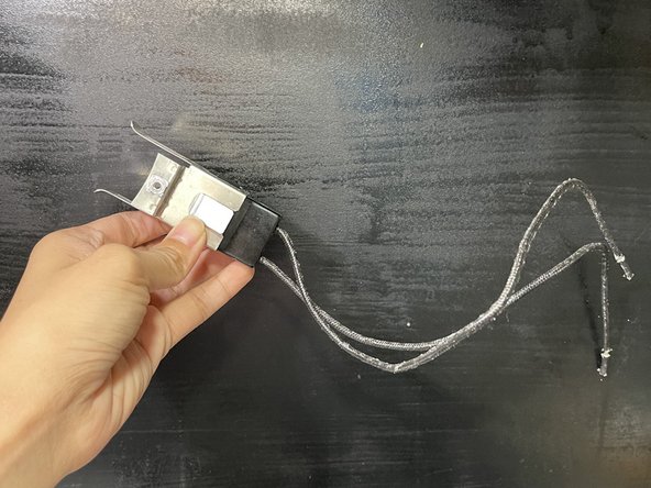
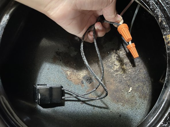
    • Pull the old receptacle block out and cut the receptacle block.

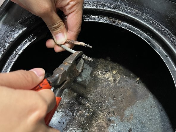
    • To strip the wires, place about an inch from the end of the wire into the mouth of the wire stripper. Carefully cut through the insulation without cutting through the copper wire.

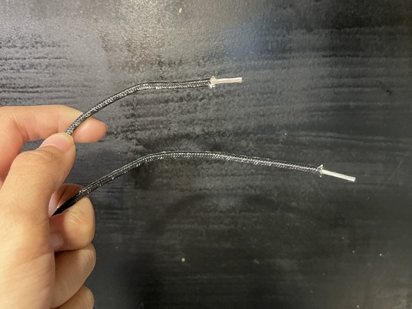
    • With the mouth of the wire strippers still closed, pull the sheathing off to the end of the wire.

  4. Stove Element Receptacle Replacement: 手順 4、 3の画像 1 Stove Element Receptacle Replacement: 手順 4、 3の画像 2 Stove Element Receptacle Replacement: 手順 4、 3の画像 3
    • Assemble the new receptacle block by snapping the metal attachment to the terminal block.

    • Click the wires into the bottom opening of the terminal block.

    • Next, strip the end of the wires.

  5. Stove Element Receptacle Replacement: 手順 5、 2の画像 1 Stove Element Receptacle Replacement: 手順 5、 2の画像 2
    • Connect the new receptacle block to the wiring harness and secure it with twist connectors.

  6. Stove Element Receptacle Replacement: 手順 6、 3の画像 1 Stove Element Receptacle Replacement: 手順 6、 3の画像 2 Stove Element Receptacle Replacement: 手順 6、 3の画像 3
    • Install the new receptacle block and tighten the mounting screw securely to ensure proper grounding.

    • Put the drip tray back.

    • Then, put the pitted scorched burner back.

  7. Stove Element Receptacle Replacement: 手順 7、 1の画像 1
    • Turn on the power supply and check for proper operation.

終わりに

To reassemble your device, follow these instructions in reverse order.

2 の人々がこのガイドを完成させました。

作成者

2人の作成者と共同で作成されました。

My Danh

メンバー登録日: 03/07/22

193 ポイント

1ガイドが承認済み

チーム

University of Memphis, Team 1-6, Cameron Fall 2022 University of Memphis, Team 1-6, Cameron Fall 2022人のメンバー

UM-CAMERON-F22S1G6

2 メンバー

1のガイドは作成済み

0 件のコメント

コメントを追加

統計データ:

過去 24時間: 0

過去 7 日: 17

過去 30 日: 47

今までの合計 1,004