メインコンテンツにスキップ

このバージョンは誤った内容を含んでいる可能性があります。最新の承認済みスナップショットに切り替えてください。

必要な工具と部品

  1. この手順は未翻訳です。 翻訳を手伝う。

    : 手順 1、 1の画像 1
    • Begin by opening the HDMI/USB port cover on the left edge.

    • Remove the three #000 headed, 3 mm long screws located underneath the port cover.

  2. この手順は未翻訳です。 翻訳を手伝う。

    : 手順 2、 1の画像 1
    • Locate and open the Micro SD slot on the top side of the device.

    • Remove the two screws located beneath the cover.

  3. この手順は未翻訳です。 翻訳を手伝う。

    : 手順 3、 2の画像 1 : 手順 3、 2の画像 2
    • Attach the suction cup to the top right area of the screen.

    • Pull to separate the screen from the rest of the device.

    • Be aware of the front camera cable that is still connected to the rest of the device.

    • Detach the display ribbon cable.

  4. この手順は未翻訳です。 翻訳を手伝う。

    : 手順 4、 1の画像 1
    • Disconnect the battery from the motherboard by pulling out the cable below the fan.

  5. この手順は未翻訳です。 翻訳を手伝う。

    : 手順 5、 1の画像 1
    • Remove the seven 3 mm Phillips #000 screws that hold the battery in place.

    • Carefully remove the battery from the back assembly.

  6. この手順は未翻訳です。 翻訳を手伝う。

    : 手順 6、 1の画像 1
    • Remove the nine 3 mm Phillips #000 screws holding in the motherboard.

  7. この手順は未翻訳です。 翻訳を手伝う。

    : 手順 7、 1の画像 1
    • Remove the black plastic dust shield by gently pulling it up.

    • You'll want to keep the sticky side up so you can replace it when reassembling. This part also functions as a shield for the sensitive camera component!

  8. この手順は未翻訳です。 翻訳を手伝う。

    : 手順 8、 3の画像 1 : 手順 8、 3の画像 2 : 手順 8、 3の画像 3
    • Before removing the motherboard, there are a few cables to disconnect.

    • Disconnect the cable connected to the top of the display.

    • Disconnect the power jack connector on the left side of the screen.

    • Disconnect the daughterboard connector located above and to the right of the WiFi chip slot.

  9. この手順は未翻訳です。 翻訳を手伝う。

    : 手順 9、 2の画像 1 : 手順 9、 2の画像 2
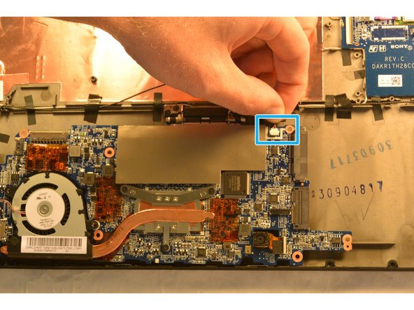
    • Gently pull the motherboard out by pulling from the right side of the board and flip it so that the motherboard now sits where the battery was and the underside is now visible.

    • There is still one cable to remove!

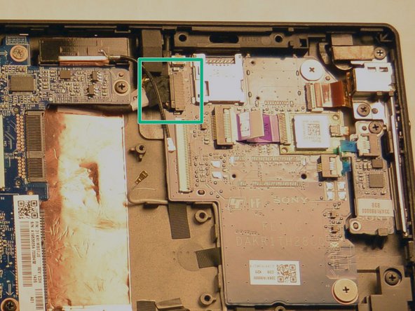
    • Remove the speaker connector located next to the SSD slot.

    • You may now remove the motherboard from the device.

ゴール

3 の人々がこのガイドを完成させました。

作成者

2人の作成者と共同で作成されました。

Alexander Bridges

メンバー登録日: 09/16/15

1,217 ポイント

7のガイドは作成済み

チーム

IUPUI, Team 1-2, Harley Fall 2015 IUPUI, Team 1-2, Harley Fall 2015人のメンバー

IUPUI-HARLEY-F15S1G2

4 メンバー

20のガイドは作成済み

0 件のコメント

コメントを追加

統計データ:

過去 24時間: 0

過去 7 日: 4

過去 30 日: 9

今までの合計 2,494