はじめに
To get to this area more easily so it can be replaced or more effectively repaired, this guide shows you how to detach the headband from the speakers.
I'm not a very advanced repairer, so maybe there are precautions I am missing but my own headphones were not the same after trying to remove the headband. Maybe it's because I had to tinker around to find out what to do, and maybe I damaged some solder joints in the process.
There is no other way to disassemble the headphones to get to the headband than the one outlined here, but consider making sure you have a soldering iron to disconnect components like the NFC antenna or repair solder joints that may possibly get damaged in this process.
必要な工具と部品
-
-
The pad is attached by 6 clips in a hexagonal pattern, shown by the arrows.
-
Starting from the top, insert an opening pick in between where the cup leather meets the plastic casing, push it in firmly, then twist it until you disengage the top clip.
-
Work round the back side, poking the pick in and twisting to disengage further clips until you can gently pull the cup away.
-
-
-
Check that you are on the Right Speaker using the indicator on the headband.
-
Use a JIS #000 screwdriver to remove the 5 6mm screws holding the Right Speaker casing in place.
-
-
-
Gently lift the casing apart like a book from the bottom.
-
-
-
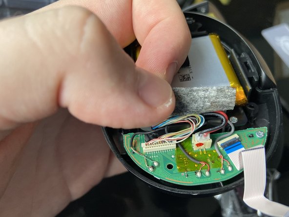
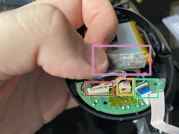
Gently peel back the foam tape with a spudger and unstick it from the two cables underneath.
-
Headband cable connector (under foam tape)
-
Battery connector (under foam tape)
-
ZIF connector for touchpad
-
Foam tape
-
-
-
Using tweezers, gently grab and pull the smaller connector up from the circuit board to disconnect the battery.
-
-
-
Using a spudger, gently flip up the latch on the ZIF connector on the circuit board connecting the touchpad.
-
Gently lift the ribbon cable away.
-
-
-
-
Extend the Left cup and fold the Right cup away via the headband.
-
This will help protect the other ear pad while you work on this one.
-
-
-
The pad is attached by 6 clips in a hexagonal pattern, shown by the arrows.
-
Starting from the top, insert an opening pick in between where the cup leather meets the plastic casing, push it in firmly, then twist it until you disengage the top clip.
-
Work round the back side, poking the pick in and twisting to disengage further clips until you can gently pull the cup away.
-
-
-
Check that you are on the Left Speaker using the indicator on the headband.
-
Use a JIS #000 screwdriver to remove the 5x 6mm screws holding the Left Speaker casing in place.
-
-
-
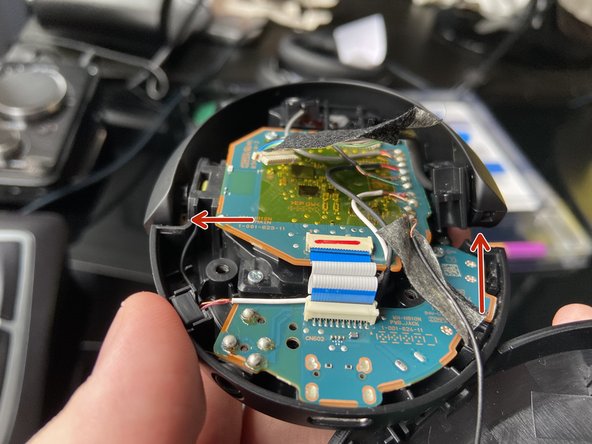
Gently lift the cup away and peek inside without fully removing it. You should see the following:
-
A thin layer of tape holding a cable going from the boards to the NFC antenna in the outer shell piece.
-
Another thin layer of tape below it holding the headband cable and NC microphone cables to the mainboard.
-
Gently pry the layer of tape holding the NFC cable.
-
Once you've done that, it should have enough slack, and then you can open it like a book from the right side.
-
-
-
With one hand holding the cup and the face plate with the NFC antenna, gently lift the foam tape holding the headband cable onto the circuit board below.
-
Just peel at the area it connects to the circuit board for now.
-
-
-
Using the pointed end of a spudger, gently pull at the edges of the sliding connector of the headband cable to disconnect it from the mainboard.
-
Gently peel the the whole headband cable up with the tape starting from the connector.
-
-
-
Rear-facing hinge held by 2 6mm JIS #000 screws
-
Front-facing hinge attached by a pivot that is socketed in the speaker casing.
-
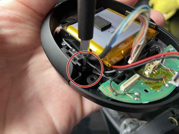
Unscrew the 6mm screws holding the rear hinge to the speaker casing.
-
-
-
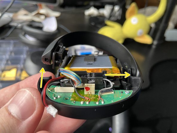
On the rear hinge, gently lift up the hinge as much as is comfortable while at the same time, gently tugging on the front hinge outwards. You should be able to create a small shift in where the hinge is sitting, which is important for the next part.
-
-
-
Gently lift up the unscrewed rear hinge as much as is comfortable over the internals.
-
Using the extra slack from lifting the rear hinge, carefully pry out the socket of the front hinge out of the speaker casing with the flat end of a spudger.
-
When you see a yellow ring appear in an opening on the top of the hinge, you're almost there.
-
Once the socket is out, gently lift the whole headband arch away from the speaker.
-
-
-
Use tweezers to gently grab the sides of the connector of the headband cable, then gently pull up and disconnect it.
-
-
-
Rear-facing hinge held by 2 6mm JIS #000 screws
-
Front-facing hinge attached by a pivot that is socketed in the speaker casing.
-
Unscrew the 6mm screws holding the rear hinge to the speaker casing.
-
-
-
On the rear hinge, gently lift up the hinge as much as is comfortable while at the same time, gently tugging on the front hinge outwards.
-
You should be able to create a small shift in where the hinge is sitting, which is important for the next part.
-
-
-
Using the same technique as the Left Speaker, use the flat end of a spudger to gently pry the socket away from the speaker casing.
-
When you see a yellow ring in the gap, you're almost there, keep going.
-
Once the socket is out, gently lift the whole headband away from the speaker.
-


Now you have full access to the headband assembly.
To reassemble your device, follow these instructions in reverse order.
Before re-installing the cups, test your headphones to make sure they turn on and work in a basic way.
Now you have full access to the headband assembly.
To reassemble your device, follow these instructions in reverse order.
Before re-installing the cups, test your headphones to make sure they turn on and work in a basic way.
2 の人々がこのガイドを完成させました。
コメント 1 件
The swivel hinge on both sides broke. This guide was instrumental, thanks so much!