メインコンテンツにスキップ
リペアコミュニティに参加 - アカウントの作成

Sony Cyber-shot DSC-T1 Motherboard Assembly Replacement

必要な工具と部品

  1. Sony Cyber-shot DSC-T1 Motherboard Assembly Replacement, Battery: 手順 1、 2の画像 1 Sony Cyber-shot DSC-T1 Motherboard Assembly Replacement, Battery: 手順 1、 2の画像 2
    • Locate the battery door at the bottom of the camera.

    • Press down on the door and slide it back. The door will pop open.

    FixBotに聞いてみる

    コメントを追加

  2. Sony Cyber-shot DSC-T1 Motherboard Assembly Replacement: 手順 2、 1の画像 1
    • Remove the battery from the door that you opened in the previous step.

    FixBotに聞いてみる

    コメントを追加

  3. Sony Cyber-shot DSC-T1 Motherboard Assembly Replacement, Disassembling Sony Cyber-shot DSC-T1 Removing Front Cover: 手順 3、 3の画像 1 Sony Cyber-shot DSC-T1 Motherboard Assembly Replacement, Disassembling Sony Cyber-shot DSC-T1 Removing Front Cover: 手順 3、 3の画像 2 Sony Cyber-shot DSC-T1 Motherboard Assembly Replacement, Disassembling Sony Cyber-shot DSC-T1 Removing Front Cover: 手順 3、 3の画像 3
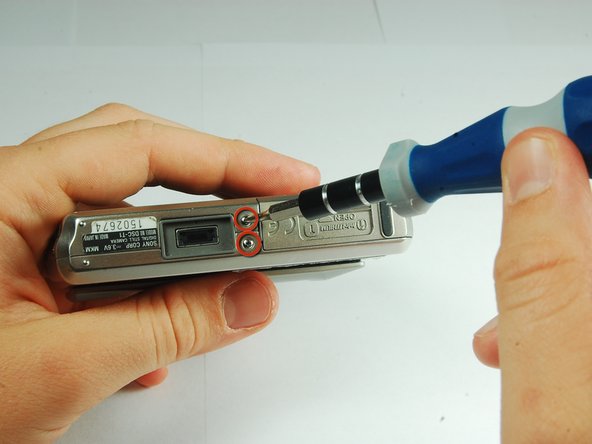
    • There are two screws on the left and right sides of the camera, and two screws on the bottom.

    • Use a PH00 screwdriver and remove the six 2.9mm screws.

    FixBotに聞いてみる

    コメントを追加

  4. Sony Cyber-shot DSC-T1 Motherboard Assembly Replacement: 手順 4、 2の画像 1 Sony Cyber-shot DSC-T1 Motherboard Assembly Replacement: 手順 4、 2の画像 2
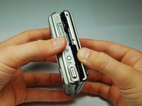
    • Use hands to gently pry the front casing away from the camera.

    FixBotに聞いてみる

    コメントを追加

  5. Sony Cyber-shot DSC-T1 Motherboard Assembly Replacement, CCD Sensor Module: 手順 5、 2の画像 1 Sony Cyber-shot DSC-T1 Motherboard Assembly Replacement, CCD Sensor Module: 手順 5、 2の画像 2
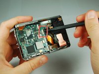
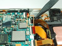
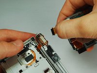
    • Use the tip of a spudger to flip up the tab on the ZIF connector securing the motherboard ribbon cable.

    • The second picture shows what these tabs look like in their open positions.

    FixBotに聞いてみる

    コメントを追加

  6. Sony Cyber-shot DSC-T1 Motherboard Assembly Replacement: 手順 6、 1の画像 1
    • Grasp the CCD Sensor Module and remove it.

    FixBotに聞いてみる

    コメントを追加

  7. Sony Cyber-shot DSC-T1 Motherboard Assembly Replacement, Flash Module: 手順 7、 3の画像 1 Sony Cyber-shot DSC-T1 Motherboard Assembly Replacement, Flash Module: 手順 7、 3の画像 2 Sony Cyber-shot DSC-T1 Motherboard Assembly Replacement, Flash Module: 手順 7、 3の画像 3
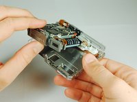
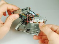
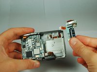
    • This camera houses a very strong capacitor (the black cylinder). Avoid touching anything around the two wires coming out of the top. Doing so will risk serious electric shock.

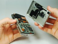
    • Carefully disengage the internal components from the casing by lifting at the bottom end and giving a gentle tug.

    • The components are still connected to the casing via cables, but they are much more maneuverable.

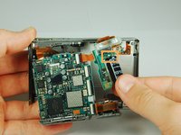
    • The flash module is shown on the right hand side.

    FixBotに聞いてみる

    コメントを追加

  8. Sony Cyber-shot DSC-T1 Motherboard Assembly Replacement: 手順 8、 2の画像 1 Sony Cyber-shot DSC-T1 Motherboard Assembly Replacement: 手順 8、 2の画像 2
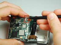
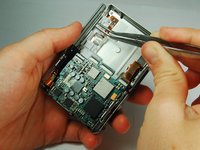
    • Use the tip of a spudger to flip up the tab on the ZIF connecter securing the motherboard ribbon cable.

    • Grasp the flash module by the bottom and remove it.

    FixBotに聞いてみる

    コメントを追加

  9. Sony Cyber-shot DSC-T1 Motherboard Assembly Replacement, Motherboard Assembly: 手順 9、 2の画像 1 Sony Cyber-shot DSC-T1 Motherboard Assembly Replacement, Motherboard Assembly: 手順 9、 2の画像 2
    この手順で使用する道具:
    Tweezers
    $4.99
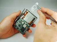
    • Use tweezers to slide the white piece on the back of the back cover to the right.

    • This will dislodge the white piece, allowing you to remove it from the back cover.

    FixBotに聞いてみる

    コメントを追加

  10. Sony Cyber-shot DSC-T1 Motherboard Assembly Replacement: 手順 10、 1の画像 1
    • Use the tip of a spudger to flip up the tab on the ZIF connector securing the motherboard ribbon cable.

    • Remove the ribbon cables from these two ZIF connectors.

    FixBotに聞いてみる

    コメントを追加

  11. Sony Cyber-shot DSC-T1 Motherboard Assembly Replacement: 手順 11、 2の画像 1 Sony Cyber-shot DSC-T1 Motherboard Assembly Replacement: 手順 11、 2の画像 2
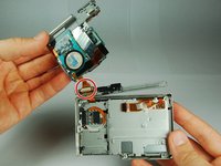
    • Lift the motherboard assembly up and rotate it so you can easily see where the internals connect to the back cover.

    • Remove the ZIF connectors from the clamp on the left end of the top piece.

    • The motherboard assembly is now separated from the back cover.

    FixBotに聞いてみる

    コメントを追加

終わりに

To reassemble your device, follow these instructions in reverse order.

キャンセル: このガイドを終了できませんでした。

作成者

10人の作成者と共同で作成されました。

iDeleted

メンバー登録日: 07/07/10

2,101 ポイント

39のガイドは作成済み

0件のガイドコメント

コメントを追加

統計データ:

過去 24時間: 0

過去 7 日: 8

過去 30 日: 39

今までの合計 2,608