メインコンテンツにスキップ

このバージョンは誤った内容を含んでいる可能性があります。最新の承認済みスナップショットに切り替えてください。

必要な工具と部品

  1. この手順は未翻訳です。 翻訳を手伝う。

    : 手順 1、 2の画像 1 : 手順 1、 2の画像 2
    • Locate the battery door at the bottom of the camera.

    • Press down on the door and slide it back. The door will pop open.

  2. この手順は未翻訳です。 翻訳を手伝う。

    : 手順 2、 1の画像 1
    • Remove the battery from the door that you opened in the previous step.

  3. この手順は未翻訳です。 翻訳を手伝う。

    : 手順 3、 3の画像 1 : 手順 3、 3の画像 2 : 手順 3、 3の画像 3
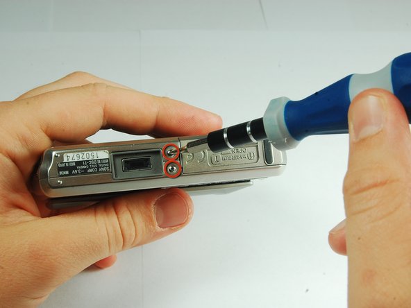
    • There are two screws on the left and right sides of the camera, and two screws on the bottom.

    • Use a PH00 screwdriver and remove the six 2.9mm screws.

  4. この手順は未翻訳です。 翻訳を手伝う。

    : 手順 4、 2の画像 1 : 手順 4、 2の画像 2
    • Use hands to gently pry the front casing away from the camera.

  5. この手順は未翻訳です。 翻訳を手伝う。

    : 手順 5、 2の画像 1 : 手順 5、 2の画像 2
    • Use the tip of a spudger to flip up the tab on the ZIF connector securing the motherboard ribbon cable.

    • The second picture shows what these tabs look like in their open positions.

  6. この手順は未翻訳です。 翻訳を手伝う。

    : 手順 6、 1の画像 1
    • Grasp the CCD Sensor Module and remove it.

  7. この手順は未翻訳です。 翻訳を手伝う。

    : 手順 7、 2の画像 1 : 手順 7、 2の画像 2
    • Use tweezers to slide the white piece on the back of the back cover to the right.

    • This will dislodge the white piece, allowing you to remove it from the back cover.

  8. この手順は未翻訳です。 翻訳を手伝う。

    : 手順 8、 1の画像 1
    • Use the tip of a spudger to flip up the tab on the ZIF connector securing the motherboard ribbon cable.

    • Remove the ribbon cables from these two ZIF connectors.

  9. この手順は未翻訳です。 翻訳を手伝う。

    : 手順 9、 2の画像 1 : 手順 9、 2の画像 2
    • Lift the motherboard assembly up and rotate it so you can easily see where the internals connect to the back cover.

    • Remove the ZIF connectors from the clamp on the left end of the top piece.

    • The motherboard assembly is now separated from the back cover.

  10. この手順は未翻訳です。 翻訳を手伝う。

    : 手順 10、 2の画像 1 : 手順 10、 2の画像 2
    • Use a PH00 screwdriver to remove the 2.9 mm phillips screw on the upper left side of the case.

  11. この手順は未翻訳です。 翻訳を手伝う。

    : 手順 11、 2の画像 1 : 手順 11、 2の画像 2
    • Remove the back frame from the LCD assembly.

    • Turn the LCD assembly over and gently pull the top bar off (which has the shutter and power buttons).

  12. この手順は未翻訳です。 翻訳を手伝う。

    : 手順 12、 1の画像 1
    • Pull the tape off that holds the LCD to the assembly.

ゴール

作成者

8人の作成者と共同で作成されました。

iDeleted

メンバー登録日: 07/07/10

2,101 ポイント

39のガイドは作成済み

0 件のコメント

コメントを追加

統計データ:

過去 24時間: 1

過去 7 日: 13

過去 30 日: 30

今までの合計 4,270