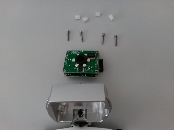
メインコンテンツにスキップ

SmartNav 4 false contact repair

必要な工具と部品

  1. SmartNav 4 false contact repair, Device  dissasembly: 手順 1、 3の画像 1 SmartNav 4 false contact repair, Device  dissasembly: 手順 1、 3の画像 2 SmartNav 4 false contact repair, Device  dissasembly: 手順 1、 3の画像 3
    • Gently open the four tabs with a small flathead screwdriver.

    • Carefully remove the black and silver cover.

  2. SmartNav 4 false contact repair: 手順 2、 2の画像 1 SmartNav 4 false contact repair: 手順 2、 2の画像 2
    • After detaching the two parts.

    • Unscrew the four hex screws with the 2mm hex key.

  3. SmartNav 4 false contact repair: 手順 3、 3の画像 1 SmartNav 4 false contact repair: 手順 3、 3の画像 2 SmartNav 4 false contact repair: 手順 3、 3の画像 3
    • Remove and separate the components

    • The problem is caused by the black insulating film between the two boards which appears to be pierced through.

  4. SmartNav 4 false contact repair: 手順 4、 1の画像 1
    • Remove the insulator, if present.

  5. SmartNav 4 false contact repair: 手順 5、 3の画像 1 SmartNav 4 false contact repair: 手順 5、 3の画像 2 SmartNav 4 false contact repair: 手順 5、 3の画像 3
    • Prepare new divider. I used a 0.4mm rigid piece of plastic.

    • You can use a rigid piece of plastic, very thin (e.g. 0.4mm)

    • Take measurements and fit it.

  6. SmartNav 4 false contact repair: 手順 6、 3の画像 1 SmartNav 4 false contact repair: 手順 6、 3の画像 2 SmartNav 4 false contact repair: 手順 6、 3の画像 3
    • Remake the device. Following the guide in reverse.

終わりに

To re-assemble your device, follow the steps in reverse order.

2 の人々がこのガイドを完成させました。

以下の翻訳者の皆さんにお礼を申し上げます:

it en

100%

これらの翻訳者の方々は世界を修理する私たちのサポートをしてくれています。 あなたも貢献してみませんか?
翻訳を始める ›

作成者

3人の作成者と共同で作成されました。

Stefano Ficacci

メンバー登録日: 05/27/16

166 ポイント

1ガイドが承認済み

2 件のコメント

Has anyone ever able to fix the issue with the smartnav not powering on

Shane Agnew - 返信

I can give only the basic level of suggestions here.

The device is not responding at all, this is the situation I'm considering here, which means: no lights and no reaction from the computer when it is connected.

You should check first the cable and the computer port, this can be done with a different cable and a different port and/or with a different device on the same cable and port, better both methods.

Once you are sure that the cable and the port are good, you need to disassemble the unit, and you may need a tester for voltage and continuity.

A visual check will tell you if there are clear signs of problems such as cracks, rust or damaged components.

Chances are that the problem is in a faulty contact (the usb connector to begin with) but it still can be a defective component (the capacitors in this case).

From here on you may need to test the power supply to the ic circuit, without short circuiting other components with the probes.

A soldering unit could be necessary then.

Stefano Ficacci - 返信

コメントを追加

統計データ:

過去 24時間: 1

過去 7 日: 2

過去 30 日: 6

今までの合計 1,256