メインコンテンツにスキップ

このバージョンは誤った内容を含んでいる可能性があります。最新の承認済みスナップショットに切り替えてください。

必要な工具と部品

  1. この手順は未翻訳です。 翻訳を手伝う。

    : 手順 1、 2の画像 1 : 手順 1、 2の画像 2
    • Remove six 1.2 mm Phillips #00 screws connected to the tripod dock and adjacent screws.

    • Remove six 1.2 mm Phillips #00 screws from the side of the camera.

  2. この手順は未翻訳です。 翻訳を手伝う。

    : 手順 2、 2の画像 1 : 手順 2、 2の画像 2
    • Use a plastic opening tool or spudger if available.

    • Using the flat end of a spudger, loosen the connection between the back panel and the device. Remove the back panel using your hands.

  3. この手順は未翻訳です。 翻訳を手伝う。

    : 手順 3、 2の画像 1 : 手順 3、 2の画像 2
    • Remove four 1.2 mm Phillips #1 screws connected to the LCD screen.

  4. この手順は未翻訳です。 翻訳を手伝う。

    : 手順 4、 3の画像 1 : 手順 4、 3の画像 2 : 手順 4、 3の画像 3
    • Flip the LCD screen over to reveal the display cable.

    • Use the tip of a spudger or your fingernail to flip up the small retaining flap on the display cable ZIF connector.

    • Be sure you are prying up on the hinged retaining flap, not the connector itself.

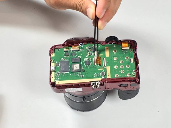
    • Using a pair of tweezers, remove the ribbon cable from its socket on the motherboard.

    • The white line on this ribbon cable marks the edge of the connection area. To reinstall, insert the cable into the connector up to this line, and then close the retaining flap. If the cable doesn’t insert easily up to (or very near to) this line, it’s probably misaligned and needs to be gently removed and repositioned.

  5. この手順は未翻訳です。 翻訳を手伝う。

    : 手順 5、 1の画像 1
    • Remove two 1.2 Phillips #00 screws connected to the motherboard.

  6. この手順は未翻訳です。 翻訳を手伝う。

    : 手順 6、 1の画像 1
    • Desolder five wires connected to the camera motherboard.

  7. この手順は未翻訳です。 翻訳を手伝う。

    : 手順 7、 2の画像 1 : 手順 7、 2の画像 2
    • Use the tip of a spudger or your fingernail to flip up the small retaining flaps on the five ZIF connectors on the motherboard.

    • Be sure you are prying up on the hinged retaining flap, not the connector itself.

    • Detach the five ribbon cables from the camera motherboard.

    • The white line on the ribbon cables mark the edge of the connection area. To reinstall, insert the cables into the connector up to this line, and then close the retaining flap. If a cable doesn’t insert easily up to (or very near to) this line, it’s probably misaligned and needs to be gently removed and repositioned.

  8. この手順は未翻訳です。 翻訳を手伝う。

    : 手順 8、 1の画像 1
    • Gently remove the motherboard.

  9. この手順は未翻訳です。 翻訳を手伝う。

    : 手順 9、 1の画像 1
    • Remove the three 1.5 mm Phillips #1 screws connected to the lens assembly.

  10. この手順は未翻訳です。 翻訳を手伝う。

    : 手順 10、 2の画像 1 : 手順 10、 2の画像 2
    • Pull the lens assembly from main body of the camera, using a spudger to pry if necessary.

ゴール

作成者

3人の作成者と共同で作成されました。

Jesse Lindsey

メンバー登録日: 05/13/16

581 ポイント

5のガイドは作成済み

チーム

Metro State, Team 1-1, Carpenter SU 2016 Metro State, Team 1-1, Carpenter SU 2016人のメンバー

MSU-CARPENTER-SU16S1G1

3 メンバー

5のガイドは作成済み

0 件のコメント

コメントを追加

統計データ:

過去 24時間: 0

過去 7 日: 4

過去 30 日: 30

今までの合計 2,708