メインコンテンツにスキップ

このバージョンは誤った内容を含んでいる可能性があります。最新の承認済みスナップショットに切り替えてください。

必要な工具と部品

  1. この手順は未翻訳です。 翻訳を手伝う。

    : 手順 1、 2の画像 1 : 手順 1、 2の画像 2
    • Place the phone so that the back is facing you. Depress the locking tab on the back of the phone with a finger or thumb.

  2. この手順は未翻訳です。 翻訳を手伝う。

    : 手順 2、 1の画像 1
    • Slide the battery toward bottom of the phone, about a quarter of an inch, to clear the hooks that keep it secured to the back of the phone.

  3. この手順は未翻訳です。 翻訳を手伝う。

    : 手順 3、 1の画像 1
    • Lift the battery away from the phone case.

  4. この手順は未翻訳です。 翻訳を手伝う。

    : 手順 4、 2の画像 1 : 手順 4、 2の画像 2
    • Grasp the antenna firmly and rotate it counterclockwise to unscrew it from the phone.

  5. この手順は未翻訳です。 翻訳を手伝う。

    : 手順 5、 1の画像 1
    • When unscrewed, pull the antenna straight up and out.

  6. この手順は未翻訳です。 翻訳を手伝う。

    : 手順 6、 2の画像 1 : 手順 6、 2の画像 2
    • Pull the guide tube free from its retaining ring and slide it out the top.

  7. この手順は未翻訳です。 翻訳を手伝う。

    : 手順 7、 1の画像 1
    • Remove the four screws using a T6 Torx screwdriver.

  8. この手順は未翻訳です。 翻訳を手伝う。

    : 手順 8、 2の画像 1 : 手順 8、 2の画像 2
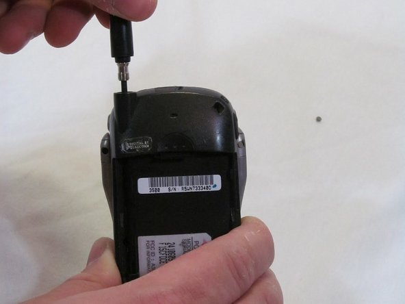
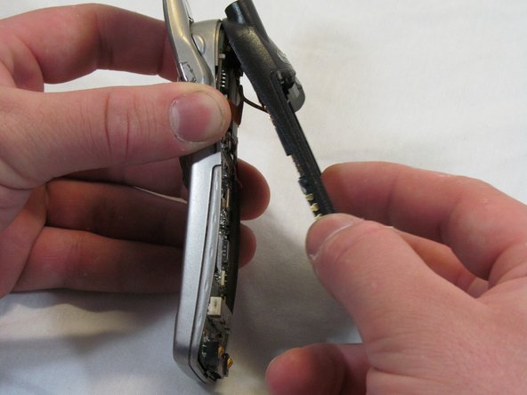
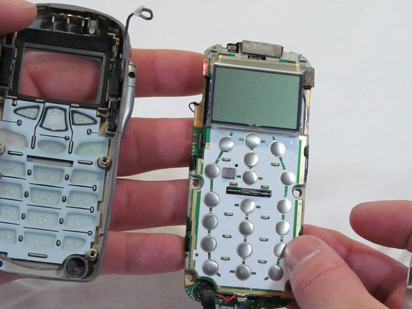
    • Work from the bottom of the phone, separating the two halves of the case.

    • Note: Take care to keep the logic board with the front case half. Part of the logic board is exposed to the sticker under the battery on the rear case half.

  9. この手順は未翻訳です。 翻訳を手伝う。

    : 手順 9、 1の画像 1
    • Angle the rear case half away from the top of the front case half, pivoting the hooks out of their clasps.

    • Caution: Do not fully separate the halves. There is an antenna ribbon connected to the logic board from the back cover.

  10. この手順は未翻訳です。 翻訳を手伝う。

    : 手順 10、 3の画像 1 : 手順 10、 3の画像 2 : 手順 10、 3の画像 3
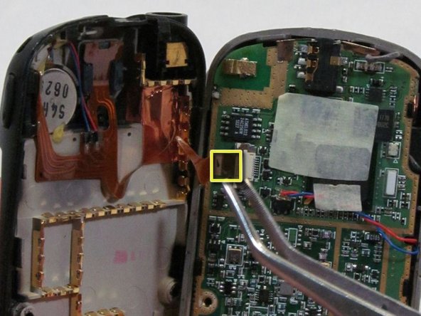
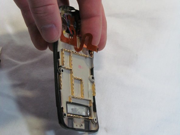
    • Disconnect the antenna ribbon cable from the logic board at the Zero Insertion Force (ZIF) connector. The brown portion of the connector lifts up to release the cable end.

    • The Back Cover is now removed. Congratulations.

  11. この手順は未翻訳です。 翻訳を手伝う。

    : 手順 11、 1の画像 1
    • Remove the connector for the earpiece speaker, located on the upper end of the logic board.

  12. この手順は未翻訳です。 翻訳を手伝う。

    : 手順 12、 1の画像 1
    • Turn the front cover over, gently prying the logic board away from the front cover. It will remain attached by two wires from the front of the board.

  13. この手順は未翻訳です。 翻訳を手伝う。

    : 手順 13、 2の画像 1 : 手順 13、 2の画像 2
    • Work the microphone out of its socket on the front cover; it will remain attached to the logic board, its wires are soldered.

    • The logic board is now removed from the phone. Congratulations.

ゴール

作成者

2人の作成者と共同で作成されました。

Brett Tomashitis

メンバー登録日: 03/09/12

36 ポイント

5のガイドは作成済み

チーム

Clemson, Team 2-6, Benson Spring 2012 Clemson, Team 2-6, Benson Spring 2012人のメンバー

CLEM-BENSON-S12S2G6

2 メンバー

10のガイドは作成済み

0 件のコメント

コメントを追加

統計データ:

過去 24時間: 3

過去 7 日: 6

過去 30 日: 7

今までの合計 817