メインコンテンツにスキップ

このバージョンは誤った内容を含んでいる可能性があります。最新の承認済みスナップショットに切り替えてください。

必要な工具と部品

  1. この手順は未翻訳です。 翻訳を手伝う。

    : 手順 1、 2の画像 1 : 手順 1、 2の画像 2
    • Using a Phillips #00 precision screwdriver, remove the seven 4mm screws (5 on the bottom of the device and 1 on each of the two sides) holding the back panel to the camera.

    • On the NX300M model, there is an additional screw under the text AMOLED behind display which should be removed before detaching the back panel of the camera.

  2. この手順は未翻訳です。 翻訳を手伝う。

    : 手順 2、 1の画像 1
    • Using a Phillips #00 precision screwdriver, remove the last 4 mm screw located inside the input ports' compartment.

  3. この手順は未翻訳です。 翻訳を手伝う。

    : 手順 3、 3の画像 1 : 手順 3、 3の画像 2 : 手順 3、 3の画像 3
    • Place a plastic opening tool into the gap between the back panel and camera body, from both the top and the bottom of camera. Carefully pry open the camera and separate the back panel.

  4. この手順は未翻訳です。 翻訳を手伝う。

    : 手順 4、 3の画像 1 : 手順 4、 3の画像 2 : 手順 4、 3の画像 3
    この手順で使用する道具:
    Tweezers
    $4.99
    購入する
    • Using tweezers or your fingers, pull the display's black ribbon from the motherboard. This frees the back panel altogether.

    • To safely remove ribbons, you would need to first unlock the holding mechanism by lifting up the black strip atop the ribbon adapter.

  5. この手順は未翻訳です。 翻訳を手伝う。

    : 手順 5、 3の画像 1 : 手順 5、 3の画像 2 : 手順 5、 3の画像 3
    • Using a Phillips #00 precision screwdriver, remove the 3mm screw holding the top panel of the camera in place. Also, remove the screws under hot shoe metal clip, otherwise you can break a piece of sensor frame leading to costly repair.

  6. この手順は未翻訳です。 翻訳を手伝う。

    : 手順 6、 3の画像 1 : 手順 6、 3の画像 2 : 手順 6、 3の画像 3
    • Using a plastic opening tool, carefully remove the top panel of the camera.

    • The top panel is held in by plastic clips. Be careful not to break these clips in removal.

  7. この手順は未翻訳です。 翻訳を手伝う。

    : 手順 7、 3の画像 1 : 手順 7、 3の画像 2 : 手順 7、 3の画像 3
    この手順で使用する道具:
    Tweezers
    $4.99
    購入する
    • Using a Phillips #00 precision screwdriver, remove the three 4mm screws holding the power switch board in place.

    • Using tweezers, gently pull the ribbon cable out of the power switch board.

  8. この手順は未翻訳です。 翻訳を手伝う。

    : 手順 8、 3の画像 1 : 手順 8、 3の画像 2 : 手順 8、 3の画像 3
    • Using a Phillips #00 precision screwdriver, remove the 4mm screw holding the jog dial in place.

    • Using tweezers, gently remove the ribbon cable attached to the jog dial.

  9. この手順は未翻訳です。 翻訳を手伝う。

    : 手順 9、 3の画像 1 : 手順 9、 3の画像 2 : 手順 9、 3の画像 3
    • The jog dial should fall out easily. If not, use a pair of tweezers to gently poke it though the power board.

  10. この手順は未翻訳です。 翻訳を手伝う。

    : 手順 10、 2の画像 1 : 手順 10、 2の画像 2
    • Using a Phillips #00 precision screwdriver, remove the four 3mm screws holding the mode dial and power switch/shutter button in place.

    • Remove the metal mounts from the underside of the dials. The dials are now free from the camera.

  11. この手順は未翻訳です。 翻訳を手伝う。

    : 手順 11、 3の画像 1 : 手順 11、 3の画像 2 : 手順 11、 3の画像 3
    • Make sure the dial slot aligns with the power switch board prior to reassembly.

ゴール

11 の人々がこのガイドを完成させました。

作成者

9人の作成者と共同で作成されました。

Andres Perez

メンバー登録日: 01/21/15

951 ポイント

5のガイドは作成済み

チーム

USF Tampa, Team 9-6, Blackwell Winter 2015 USF Tampa, Team 9-6, Blackwell Winter 2015人のメンバー

USFT-BLACKWELL-W15S9G6

4 メンバー

10のガイドは作成済み

3 件のコメント

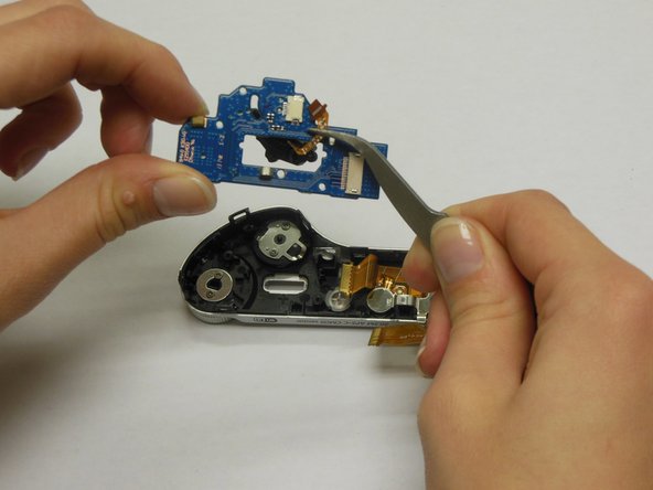
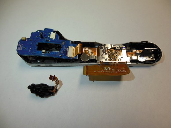
Thanks, this was useful. Camera was switching modes randomly. I didn't replace the PCB however, just opened and sprayed a lot of silicon oil into the dial.

Marian Juranyi - 返信

Thanks! I fixed my camera. But i think step 10 not necessary.

odiss2000 - 返信

Perfect ! My Camera was switching modes randomly too. I changed the board from step 9 with a new part found on Ebay. Thank you :-)

sgexfabry - 返信

コメントを追加

統計データ:

過去 24時間: 4

過去 7 日: 27

過去 30 日: 87

今までの合計 9,496