メインコンテンツにスキップ

このバージョンは誤った内容を含んでいる可能性があります。最新の承認済みスナップショットに切り替えてください。

必要な工具と部品

  1. この手順は未翻訳です。 翻訳を手伝う。

    : 手順 1、 1の画像 1
    • Slide the battery cover downwards with pressure focused on the center of the cover.

    • Lift the cover off of the phone.

  2. この手順は未翻訳です。 翻訳を手伝う。

    : 手順 2、 1の画像 1
    • Grasp the bottom left and right corners of the battery and lift it from its housing.

  3. この手順は未翻訳です。 翻訳を手伝う。

    : 手順 3、 1の画像 1
    • Remove the four black 7.30 mm screws surrounding the battery housing using a Phillips #00 Screwdriver.

  4. この手順は未翻訳です。 翻訳を手伝う。

    : 手順 4、 3の画像 1 : 手順 4、 3の画像 2 : 手順 4、 3の画像 3
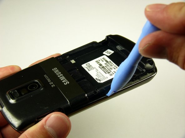
    • The rear case is firmly attached to the phone with clips. Do not be afraid to use a little extra force.

    • Insert the Plastic Opening Tool in between the front and rear cases.

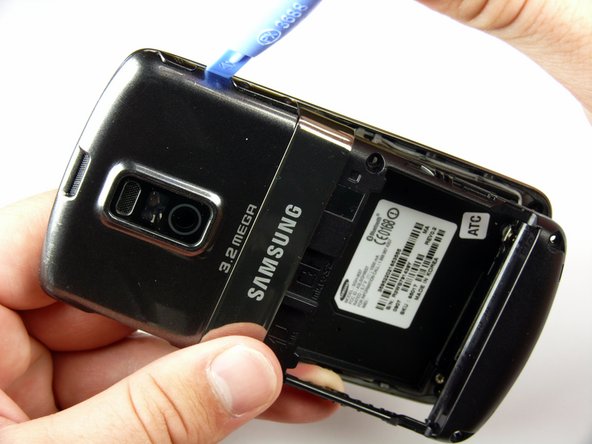
    • Pry with the Plastic Opening Tool around all edges of the phone until you free all the clips.

  5. この手順は未翻訳です。 翻訳を手伝う。

    : 手順 5、 1の画像 1
    • Lift the rear case off of the phone.

  6. この手順は未翻訳です。 翻訳を手伝う。

    : 手順 6、 1の画像 1
    • Remove the two silver 4.30 mm screws on either side of the antenna using a Phillip's #00 Screwdriver.

  7. この手順は未翻訳です。 翻訳を手伝う。

    : 手順 7、 3の画像 1 : 手順 7、 3の画像 2 : 手順 7、 3の画像 3
    • There is a wire under the antenna connecting it to the Motherboard. Do not pull off the antenna just yet.

    • Use a spudger to remove the wire connector under the antenna.

  8. この手順は未翻訳です。 翻訳を手伝う。

    : 手順 8、 1の画像 1
    • Remove the two black 7.30 mm screws on the top right and left corners of the Motherboard using a Phillips #00 Screwdriver.

    • Remove the silver 4.50 mm screw located below the speaker using a Phillips #00 Screwdriver.

  9. この手順は未翻訳です。 翻訳を手伝う。

    : 手順 9、 2の画像 1 : 手順 9、 2の画像 2
    • Use the spudger to detach the speaker ribbon cable.

  10. この手順は未翻訳です。 翻訳を手伝う。

    : 手順 10、 1の画像 1
    • Lift the speaker out of its compartment.

  11. この手順は未翻訳です。 翻訳を手伝う。

    : 手順 11、 1の画像 1
    • Remove the power and volume buttons on the right side of the Motherboard.

  12. この手順は未翻訳です。 翻訳を手伝う。

    : 手順 12、 2の画像 1 : 手順 12、 2の画像 2
    • Use a spudger to detach the camera ribbon cable.

    • Lift the camera off of the Motherboard.

  13. この手順は未翻訳です。 翻訳を手伝う。

    : 手順 13、 2の画像 1 : 手順 13、 2の画像 2
    • Use a spudger to disconnect the white antenna wire on the bottom right corner of the Motherboard.

  14. この手順は未翻訳です。 翻訳を手伝う。

    : 手順 14、 3の画像 1 : 手順 14、 3の画像 2 : 手順 14、 3の画像 3
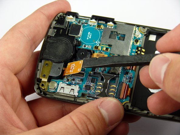
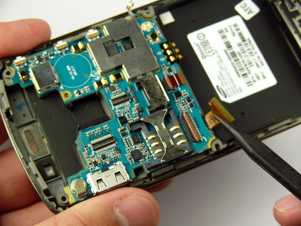
    • Use a Plastic Opening Tool to lift the flaps of the ZIF connectors to release the ribbon cables near the bottom of the Motherboard.

    • Use a spudger to carefully pull the ribbon cables away from the ZIF connectors.

  15. この手順は未翻訳です。 翻訳を手伝う。

    : 手順 15、 2の画像 1 : 手順 15、 2の画像 2
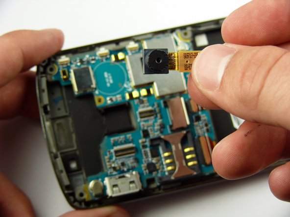
    • There is a ribbon cable under the Motherboard connecting it to the LCD. Do not pull off the Motherboard just yet.

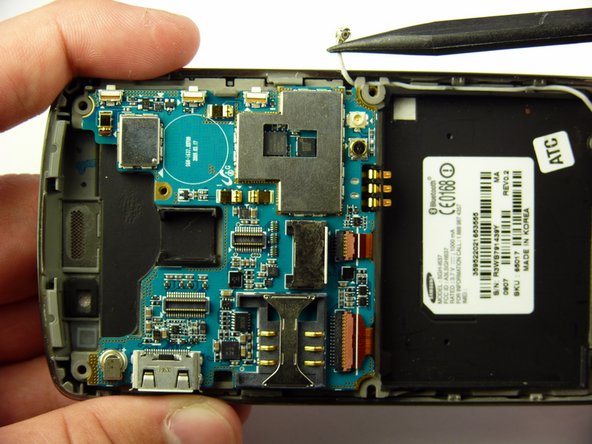
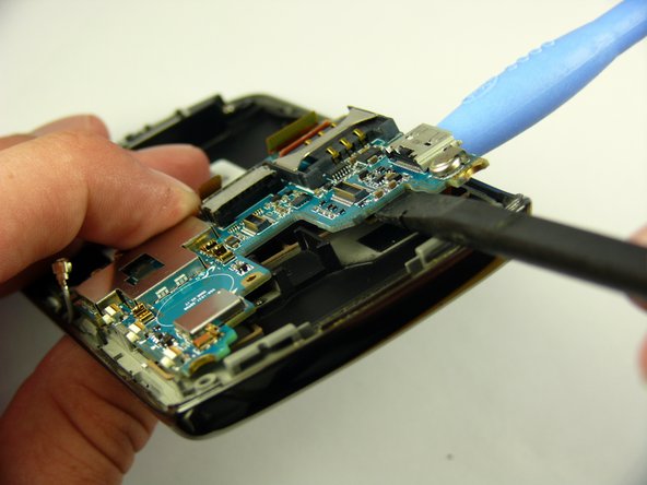
    • Insert the Plastic Opening Tool under the upper left corner of the Motherboard to help reveal the ribbon cable.

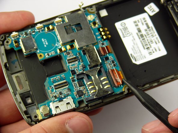
    • Use a spudger to disconnect the Motherboard ribbon cable.

  16. この手順は未翻訳です。 翻訳を手伝う。

    : 手順 16、 1の画像 1
    • Lift the Motherboard off of the phone.

  17. この手順は未翻訳です。 翻訳を手伝う。

    : 手順 17、 3の画像 1 : 手順 17、 3の画像 2 : 手順 17、 3の画像 3
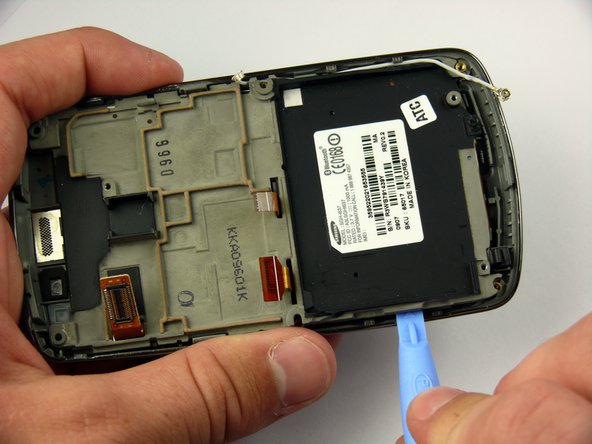
    • The LCD frame is firmly attached to the phone with clips. Do not be afraid to use a little extra force.

    • Insert the Plastic Opening Tool between the LCD frame and the front case of the phone.

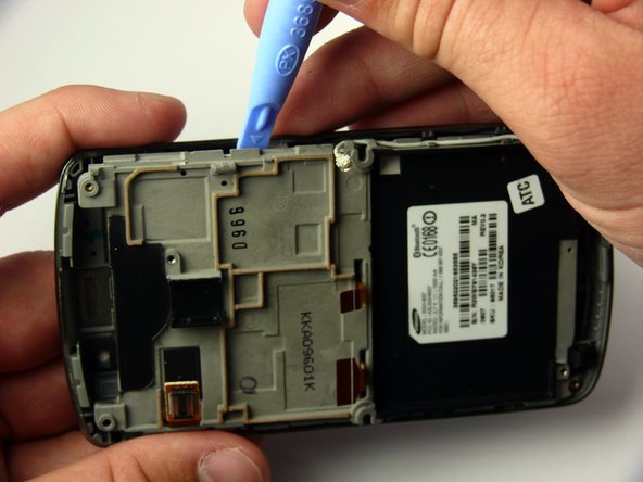
    • Slide the Plastic Opening Tool around the LCD frame to detach all of the clips.

  18. この手順は未翻訳です。 翻訳を手伝う。

    : 手順 18、 2の画像 1 : 手順 18、 2の画像 2
    • Lift up the LCD frame.

  19. この手順は未翻訳です。 翻訳を手伝う。

    : 手順 19、 3の画像 1 : 手順 19、 3の画像 2 : 手順 19、 3の画像 3
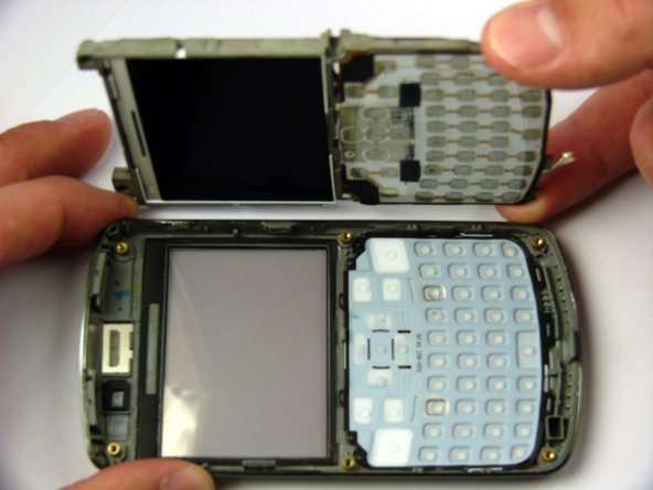
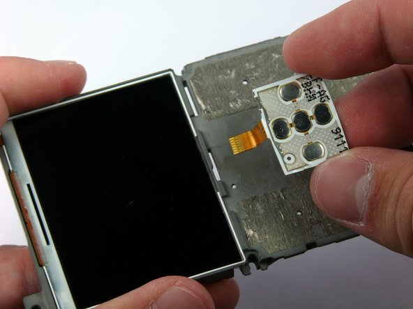
    • The keyboard ribbon cable passes through the LCD frame. Be careful not to rip the ribbon cable when removing the keyboard.

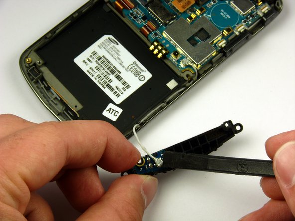
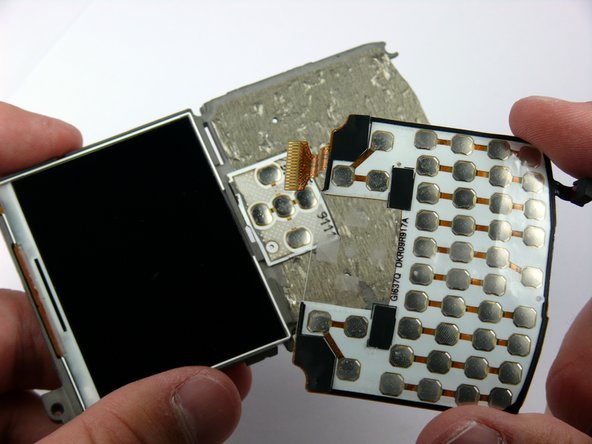
    • The keyboard and directional keys are glued separately to the LCD frame.

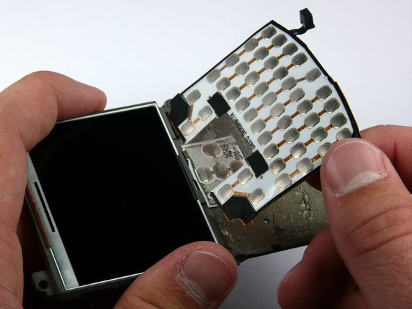
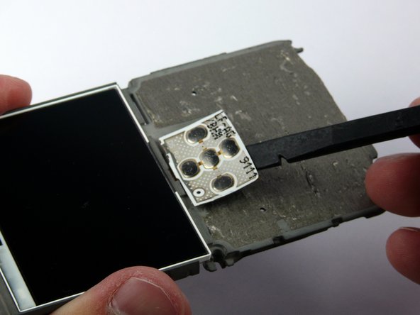
    • Insert the spudger between the keyboard and the frame.

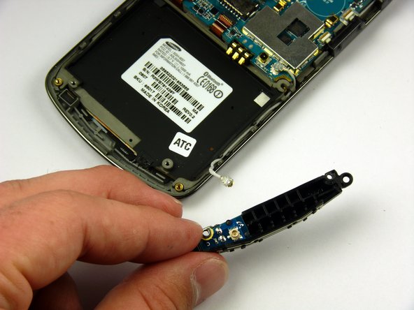
    • Peel the keyboard off by sliding the spudger back and forth across the LCD frame.

  20. この手順は未翻訳です。 翻訳を手伝う。

    : 手順 20、 3の画像 1 : 手順 20、 3の画像 2 : 手順 20、 3の画像 3
    • Insert the spudger between the directional keys and the frame.

    • Peel the directional keys off by sliding the spudger back and forth across the LCD frame.

ゴール

ある他の人がこのガイドを完成しました。

作成者

5人の作成者と共同で作成されました。

Jaime Serrano

メンバー登録日: 04/11/11

59 ポイント

2のガイドは作成済み

チーム

Cal Poly, Team 24-57, Amido Spring 2011 Cal Poly, Team 24-57, Amido Spring 2011人のメンバー

CPSU-AMIDO-S11S24G57

4 メンバー

7のガイドは作成済み

0 件のコメント

コメントを追加

統計データ:

過去 24時間: 1

過去 7 日: 1

過去 30 日: 1

今までの合計 2,054