メインコンテンツにスキップ

このバージョンは誤った内容を含んでいる可能性があります。最新の承認済みスナップショットに切り替えてください。

必要な工具と部品

  1. , バッテリー: 手順 1、 1の画像 1
    • デバイスを分解する前に、デバイスの電源が切れていることを確認してください。

    • メモリカードスロットの上部に小さな金属のスパッジャーを差し込み、デバイスと背面カバーを分離します。

    • スパッジャはデバイスと背面カバーを分離するために使用され、この時点では背面カバーは取り外せません。

    • できればナイロンスパッジャーを使用して背面カバーを分離させてください。そうすればデバイスが傷つく可能性が低くなります。

  2. : 手順 2、 2の画像 1 : 手順 2、 2の画像 2
    • バックカバーを取り外すには、手順1のスパッジャーより少し大きなメタル製スパッジャーを使用します。 スパッジャーをメモリカードスロットの上部に差し込み、デバイスの周囲をスライドさせます。

    • 2番目の画像は、背面カバーを取り外した後のデバイス内部を写した画像です。

  3. : 手順 3、 1の画像 1
    • 先の曲がった精密ピンセットを使用してマザーボードから電源コネクタを外します。

    • ピンセットでマザーボードに触れないようご注意ください。 ピンセットなどの金属製ツールは、マザーボードを傷つけ、損傷を引き起こす可能性があります。

  4. : 手順 4、 3の画像 1 : 手順 4、 3の画像 2 : 手順 4、 3の画像 3
    • スパッジャーの平らな端を使用して、バッテリーをデバイスから引き離してください。

    • 別の方法としては、スパッジャーを使用してバッテリーを緩め、PULL (HANDS ONLY)と表記されたタブを引っ張ってバッテリーを取り外すことです。

    • バッテリーが取り外されるとデバイスは2枚目の画像のようになります。

  5. この手順は未翻訳です。 翻訳を手伝う。

    : 手順 5、 2の画像 1 : 手順 5、 2の画像 2
    • Use a spudger to lift up and release the press-fit display cable connector from the motherboard.

  6. この手順は未翻訳です。 翻訳を手伝う。

    : 手順 6、 2の画像 1 : 手順 6、 2の画像 2
    • Use a spudger to lift up and release the ZIF connector; gently pull the rear facing camera ribbon cable free.

    • Use a pair of tweezers to gently secure the camera and lift it out of the frame.

    • If you're unable to secure the camera with tweezers, slide an opening pick between the frame and the camera and lift the camera out.

  7. この手順は未翻訳です。 翻訳を手伝う。

    : 手順 7、 1の画像 1
    • Use a spudger to flip the front-facing camera ZIF connector up; gently pull the ribbon cable free.

    • Use tweezers to gently remove the front facing camera from the frame.

  8. この手順は未翻訳です。 翻訳を手伝う。

    : 手順 8、 1の画像 1
    • Use the flat end of a spudger to lift up and disconnect the LCD screen press-fit connector.

  9. この手順は未翻訳です。 翻訳を手伝う。

    : 手順 9、 1の画像 1
    • Use the flat end of a spudger to lift up and disconnect the 3.5mm headset jack press-fit connector.

  10. この手順は未翻訳です。 翻訳を手伝う。

    : 手順 10、 1の画像 1
    • Use a PH000 screwdriver to remove the two 3 mm screws that connect the USB port shield to the midframe.

  11. この手順は未翻訳です。 翻訳を手伝う。

    : 手順 11、 2の画像 1 : 手順 11、 2の画像 2
    • Use a PH000 screwdriver to remove the two 3 mm screws on the left side of the motherboard.

  12. この手順は未翻訳です。 翻訳を手伝う。

    : 手順 12、 3の画像 1 : 手順 12、 3の画像 2 : 手順 12、 3の画像 3
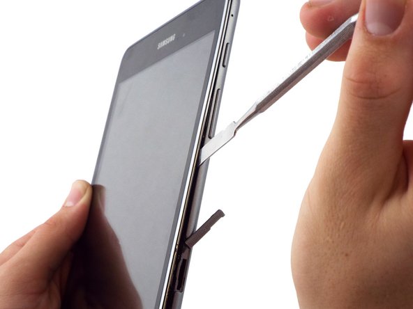
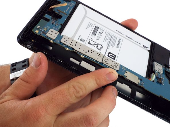
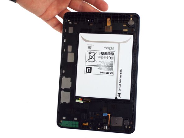
    • Lift the motherboard free from the power and volume button side.

    • You may use a spudger to assist in gently lifting the motherboard up from the button side.

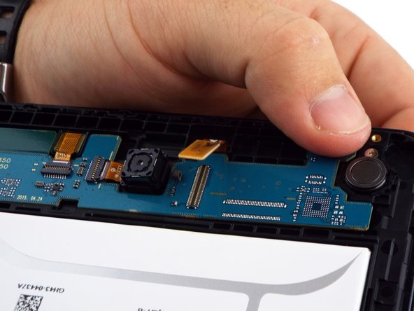
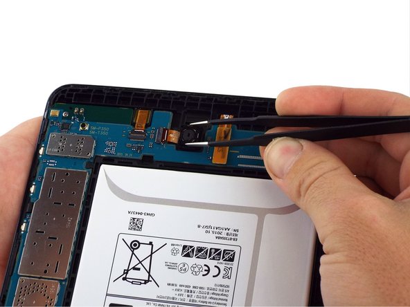
    • A small plastic bracket secures the motherboard to the frame; lift the motherboard from the power and volume button side first, and slide away from the bracket.

ゴール

13 の人々がこのガイドを完成させました。

作成者

1人の作成者と共同作成されました。

Richard

メンバー登録日: 02/07/17

30,037 ポイント

11のガイドは作成済み

チーム

iFixit iFixit人のメンバー

Staff

135 メンバー

16,817のガイドは作成済み

3 件のコメント

Where is the rest of this guide? Just stops after removing motherboard :[

chrischevrier - 返信

It appears that it is intended to remove all parts from the case (battery and motherboard) and install them in a new body with a good screen attached.

Ben D -

After removing the motherboard, I continued with disassembly by following the iFixit guide for the Digitizer removal.

( Samsung Galaxy Tab A Digitizer Replacement )

After removing the glass/digitizer, I was able to remove the LCD relatively easy by pushing it through the gaps on the back end of the frame. It appeared to not have any adhesive holding it in place. I was replacing the LCD and the digitizer in my case so I was I bit more careless with the removal of those components. I did place a bit of adhesive on the new LCD replacement and everything fit back snuggly.

Uriel Garcia -

コメントを追加

統計データ:

過去 24時間: 11

過去 7 日: 33

過去 30 日: 153

今までの合計 16,008