メインコンテンツにスキップ

このバージョンは誤った内容を含んでいる可能性があります。最新の承認済みスナップショットに切り替えてください。

必要な工具と部品

  1. この手順は未翻訳です。 翻訳を手伝う。

    : 手順 1、 2の画像 1 : 手順 1、 2の画像 2
    • Power the device down completely

    • Remove the SD card from the SD card slot.

  2. この手順は未翻訳です。 翻訳を手伝う。

    : 手順 2、 2の画像 1 : 手順 2、 2の画像 2
    • Use the prying tool to separate the front and rear panels by slipping the tool underneath the screen edge and sliding it around the entire device.

    • Be sure to unclip all of the clips on the back panel or it will be difficult for you to pull it off and may damage the tablet.

  3. この手順は未翻訳です。 翻訳を手伝う。

    : 手順 3、 2の画像 1 : 手順 3、 2の画像 2
    • Remove the battery Flex Cable from its socket by placing the pry tool under the wires and gently prying it out.

    • When you are placing in the new battery, it helps to connect the socket first or else it becomes difficult to properly align once the battery is in place.

  4. この手順は未翻訳です。 翻訳を手伝う。

    : 手順 4、 3の画像 1 : 手順 4、 3の画像 2 : 手順 4、 3の画像 3
    • Using the Phillips precision screw driver remove the six 4 mm screws holding the battery in place.

    • Once the battery is loose, remove as shown.

  5. この手順は未翻訳です。 翻訳を手伝う。

    : 手順 5、 1の画像 1
    • Using the Phillips #00 precisions screwdriver, remove the 12 4mm screws holding in the motherboard.

  6. この手順は未翻訳です。 翻訳を手伝う。

    : 手順 6、 3の画像 1 : 手順 6、 3の画像 2 : 手順 6、 3の画像 3
    • Release all flex cable connections at the bottom section of the motherboard.

    • Using the plastic pry tool release connections for both loudspeakers.

    • Once disconnected gently remove the loudspeakers from the device.

  7. この手順は未翻訳です。 翻訳を手伝う。

    : 手順 7、 3の画像 1 : 手順 7、 3の画像 2 : 手順 7、 3の画像 3
    • Release all flex cables on the right side of the device motherboard as shown.

    • Using the plastic pry tool, release the touch screen flex cable from its socket.

    • With the same tool release the LCD screen flex cable form its socket.

  8. この手順は未翻訳です。 翻訳を手伝う。

    : 手順 8、 2の画像 1 : 手順 8、 2の画像 2
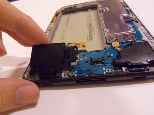
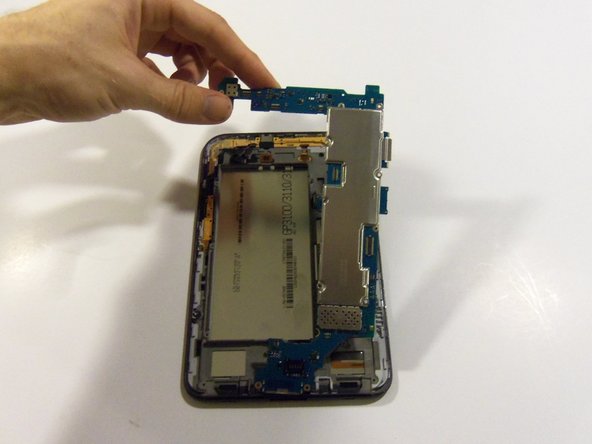
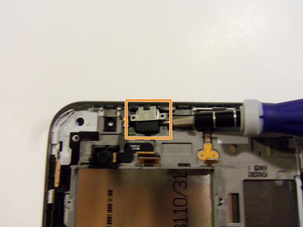
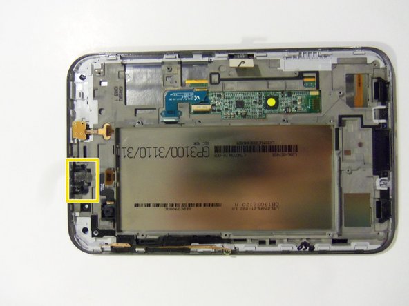
    • Release all flex cables on the upper portion of the motherboard.

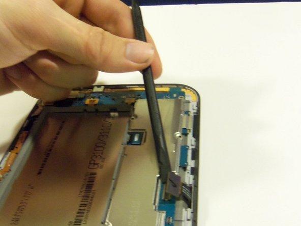
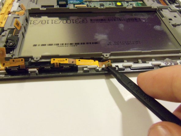
    • Using the plastic pry tool release the sensor flex cable from its socket.

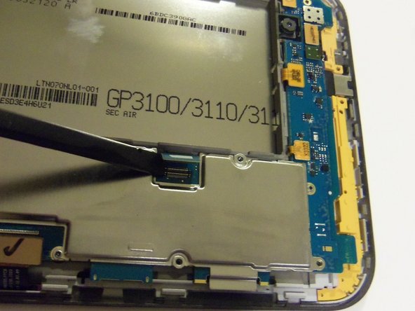
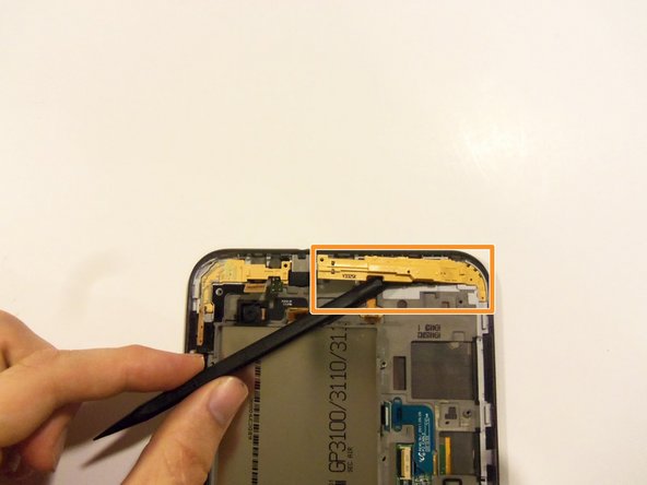
    • With the same tool release the camera flex cable from its socket.

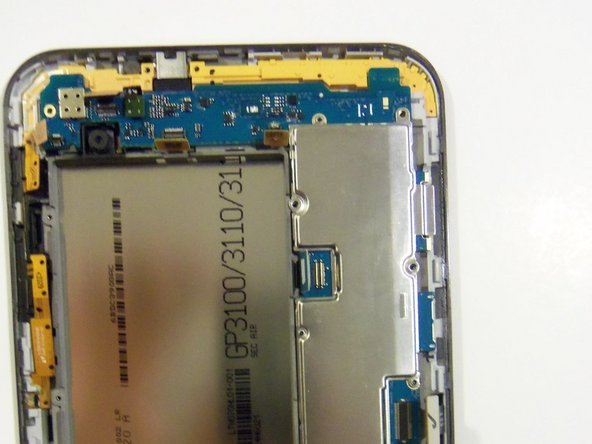
    • Release the front camera flex cable from its socket.

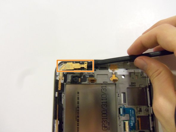
    • Release the side button's flex cable from its socket.

  9. この手順は未翻訳です。 翻訳を手伝う。

    • There is one more Flex cable to remove, it's to the right of the front camera connector (see previous picture with connector highlighted in yellow box). It connects the top microphone and headphone jack.

  10. この手順は未翻訳です。 翻訳を手伝う。

    : 手順 10、 2の画像 1 : 手順 10、 2の画像 2
    • Gently remove the motherboard from the device.

    • Be sure no flex cables get caught on the motherboard while you are removing it or the flex cables may become damaged.

    • It is easier to begin lifting the motherboard from the top rather than the bottom.

  11. この手順は未翻訳です。 翻訳を手伝う。

    : 手順 11、 2の画像 1 : 手順 11、 2の画像 2
    • Release the button flex cable using the plastic spudger tool.

    • Be careful when removing the flex cable due to how small the button flex cable is and the strong adhesive that holds it in place.

  12. この手順は未翻訳です。 翻訳を手伝う。

    : 手順 12、 3の画像 1 : 手順 12、 3の画像 2 : 手順 12、 3の画像 3
    • Remove the main camera using the plastic spudger tool.

    • Using the plastic spudger tool, remove the two main spacers.

  13. この手順は未翻訳です。 翻訳を手伝う。

    : 手順 13、 1の画像 1
    この手順で使用する道具:
    Tweezers
    $4.99
    購入する
    • Remove the front facing camera using the precision tweezers.

  14. この手順は未翻訳です。 翻訳を手伝う。

    : 手順 14、 3の画像 1 : 手順 14、 3の画像 2 : 手順 14、 3の画像 3
    • Remove the sensor flex cable using the flat-head screwdriver.

    • Remove the cover that is over the headphone jack using the precision flat-head screwdriver.

    • Remove the headphone jack using the precision flat-head screwdriver.

    • Be careful removing the headphone jack and take your time because the adhesive is very strong.

  15. この手順は未翻訳です。 翻訳を手伝う。

    : 手順 15、 3の画像 1 : 手順 15、 3の画像 2 : 手順 15、 3の画像 3
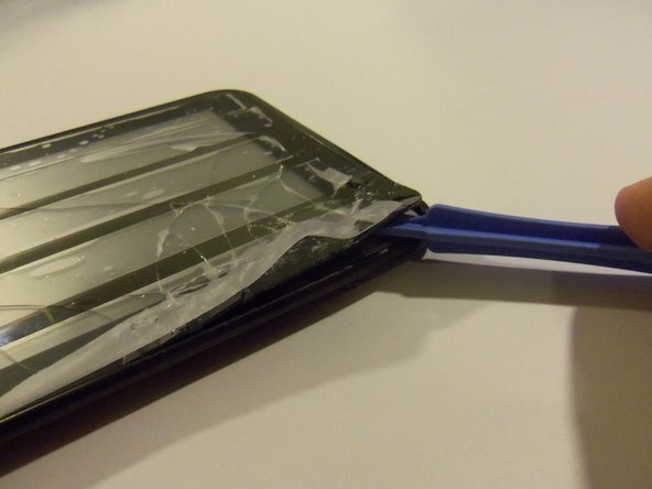
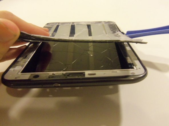
    • Place tape over the front of the touch screen to catch broken glass. The wider the tape the better.

    • Heat up the touch screen in some way to release the strong adhesive.

    • Using the safe pry tool, pry up the edge of the touch screen and slowly work your way around the entire device.

  16. この手順は未翻訳です。 翻訳を手伝う。

    : 手順 16、 1の画像 1
    • Congratulations, this is what your device should look like after the touch screen has been removed.

ゴール

4 の人々がこのガイドを完成させました。

作成者

6人の作成者と共同で作成されました。

Paul

メンバー登録日: 03/05/15

2,183 ポイント

4のガイドは作成済み

チーム

Sam Houston State, Team 11-5, Blackburne Winter 2015 Sam Houston State, Team 11-5, Blackburne Winter 2015人のメンバー

SHSU-BLACKBURNE-W15S11G5

3 メンバー

4のガイドは作成済み

0 件のコメント

コメントを追加

統計データ:

過去 24時間: 1

過去 7 日: 7

過去 30 日: 24

今までの合計 2,305