はじめに
ステータスライトや赤外線センサーを含むヘッドフォンジャックアセンブリを交換するにはこの手順をご利用ください。
必要な工具と部品
-
-
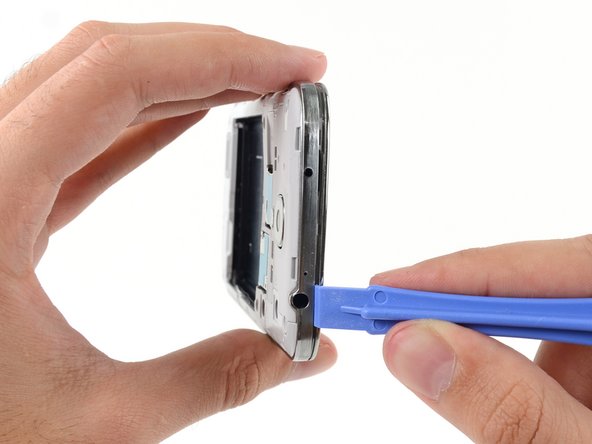
ツールを差し込んだコーナー付近から背面ケースを持ち上げて、本体から取り出します。
I purchased a blue plastic opening tool(AKA: Spudge) like the one used in the above Step 1 rear cover pic and found the divot and was able to take off the rear cover as per the “Step 2 “ instructions.
-
-
-
プラスチック製の開口ツールや指の爪をバッテリーコンパートメントの溝に差し込み、上向きにバッテリーを押し上げます。
-
iPhoneからバッテリーを取り出します。
-
-
-
プラスチック製の開口ツールや指の爪を使って、SIMカードを奥まで軽くおします。カチッという音が鳴ったら止めてください。
-
カードから手を離すとスロットからカードが出てきます。
-
SIMカードを取り出します。
Looks easy but doesn't work. No one has a plastic opening tool. Using fingernail, you can press SIM card into slot but it does not pop out so you can remove it.
I agree with the comment above
I also don't have a plastic tool and my finger nail won't pop the card out.
Grethe Montano. September 22
-
-
-
ディスプレイアセンブリに留められたミッドフレームから 4.0 mm #00プラスネジを9本外します。
How much cost will be on replace a midframe
I purchased a 1.5x40mm Phillips screw driver and was able to remove all 9 40mm screws from the midframe as per the Step 6 Midframe instructions.
-
-
-
デバイス本体サイドにある音量ボタン側から作業を始めます。ディスプレイガラス周辺のクロムベゼルと大きなクロムの淵部分の間にプラスチック製の開口ツールを差し込みます。この両側の繋ぎ目を探してください。
-
開口ツールを繋ぎ目にそってスライドします。進みながらプラスチッククリップを外します。
I used same tool as in the photo and i broke the display. I think you should use a very thin plastic tool, such as a credit card but even more thin and flexible.
I purchased a blue plastic opening tool(AKA: Spudger) and was able to remove the midframe from the display assembly as per the Step 7. I had to hold the cell phone firmly in my left hand while I gently forced the spudger between the chrome bezel and the midframe with my right hand and heard plastics clips separate and saw the midframe start to separate from the display assembly. Don’t be afraid to get that spudger in and just gently go down the side of the phone and you will hear the plastics clips detach and the midframe to separate more and more until you are able to separate them 100%. I started at the volume button side of the phone in Step 7 and ended at the power button side in Step 9.
-
-
-
-
本体の角周辺も続けてこじ開けます。
-
開口ツールをミッドフレームとデバイスの底側のディスプレイの間の繋ぎ目に沿ってスライドさせ、プラスチックのクリップを外していきます。
I purchased a blue plastic opening tool(AKA: Spudger) and was able to remove the midframe from the display assembly as per the Step 7. I had to hold the cell phone firmly in my left hand while I gently forced the spudger between the chrome bezel and the midframe with my right hand and heard plastics clips separate and saw the midframe start to separate from the display assembly. Don’t be afraid to get that spudger in and just gently go down the side of the phone and you will hear the plastics clips detach and the midframe to separate more and more until you are able to separate them 100%. I started at the volume button side of the phone in Step 7 and ended at the power button side in Step 9.
-
-
-
開口ツールをデバイス本体上部周辺でスライドさせながらクリップの残りを外し、ディスプレイアセンブリからミッドフレームを外します。
On my phone, there was another clip holding the white midframe to the battery compartment, in the middle of the top edge of the battery compartment, near the battery contacts. If you don't release that before removing the midframe, it is easy to break.
I purchased a blue plastic opening tool(AKA: Spudger) and was able to remove the midframe from the display assembly as per the Step 7. I had to hold the cell phone firmly in my left hand while I gently forced the spudger between the chrome bezel and the midframe with my right hand and heard plastics clips separate and saw the midframe start to separate from the display assembly. Don’t be afraid to get that spudger in and just gently go down the side of the phone and you will hear the plastics clips detach and the midframe to separate more and more until you are able to separate them 100%. I started at the volume button side of the phone in Step 7 and ended at the power button side in Step 9. In Step 10 just make sure all the plastic clips are separated from the midframe and the display assembly so you can pull them apart 100% without breaking them.
-
-
-
ディスプレイアセンブリからミッドフレームを取り出します。
My Sprint S4 was slightly different then the one pictured above but I just completed this repair in under 10 minutes.. It would have been slightly quicker but fooling around with those little screws can be irritating if you have big hands.
-
-
-
スパッジャーの平面側先端を使って、USBボードコネクターの接続を外します。
-
正面カメラケーブルのコネクターの接続を外します。
-
イヤホンスピーカーのアセンブリケーブルコネクターの接続を外します。
-
-
-
ヘッドホンジャックアセンブリのケーブルコネクターの接続を外します。
-
ディスプレイ/デジタイザーケーブルコネクターの接続を外します。
-
アンテナケーブルコネクターの接続を外します。
My model had an antenna connection next to the usb board connector in addition to the antenna connection near the display cable connector.
That's point a, on the daughter board (where the USB is located is point b. You must connect it from a to b
I could not get the screen connector to fit on with the motherboard assembly in place. I had to remove the motherboard assembly, attach the screen connector, and then carefully replace the motherboard assembly, with the screen connector still attached..
Same as Tom4G above. When trying to connect the screen connector, it would not give me that nice clear snap indicating a positive connection. The phone powered up with no screen. So, I disconnected the other connectors again, lifted the motherboard out and connected the screen connector by pinching it with finger and thumb from both sides of the motherboard, this time getting a nice snap when it engaged.
speedrzr -
-
-
-
ディスプレイアセンブリに留められたヘッドフォンジャックアセンブリから2.4 mm #00プラスネジを1本外します。
-
-
-
ヘッドフォンジャックアセンブリを取り出します。
I had a quick question there's a little white rubber circular gasket piece that the headphone jack covers up
What's that piece called?
The small rectangular milky-white silicon gasket appears to be a diffuser for ambient light sensor. I removed it with a small screwdriver, and replaced it in the same location in my new screen assembly.
The small rectangular milky-white silicon gasket appears to be a diffuser for an ambient light sensor. I prised it out of the old assembly and placed it in the new screen assembly. I also started transferring the components as they were removed from the old screen, so the head-phone jack went straight into the new at this point. I may regret that later…
The angle of the picture here makes it appear like the head phone jack needs to be slid out of the top of the phone. This is impossible due to small bits of plastic holding it in at the top. If you're having trouble, the headphone jack is in fact supposed to lift straight up out of the phone.
Additionally, there might be a small amount of adhesive holding the headphone jack to the board (there was some in my device). Apply a bit of heat to loosen it up, if needed.
it is easy to pop off, if you apply pressure to the right point. Using a plastic pair of tweezers or a pry tool, push at the lower right corner and gradually increase the pressure, if you apply enough pressure it will just pop right off.
-


デバイスを再組み立てする際は、これらの手順を逆の順番に従って作業を進めてください。
デバイスを再組み立てする際は、これらの手順を逆の順番に従って作業を進めてください。
37 の人々がこのガイドを完成させました。
以下の翻訳者の皆さんにお礼を申し上げます:
100%

Midori Doiさんは世界中で修理する私たちを助けてくれています! あなたも貢献してみませんか?
翻訳を始める ›


8 件のコメント
I accidentally inserted an electric pin instead of the auxiliary jack into the head phone jack assembly. There was a loud screeching sound and ever since then the head phones do not work. However, I can play music through the phone speaker and also with Bluetooth. I cannot listen to music with my ear buds or head phones or with auxiliary speakers. I have replaced the jack assembly with a new one and yet it is the same. What more can I do to rectify this?
Did you ever get help on this? Having the same problem.
Me too have same problem....did u got it fixed or not?...if yes how u did it...?
reone -
I too am having this issue. I assume we have fried the amp for external audio with wtv current we happened to let touch our aux ports. Sounds like I bigger issue to fix. Just still wondering if I can.
Where do you even get the part?
Thanks to Sam Lionheart for this guide. It was clear and easy to follow. It gave me the instructions I needed to solve my problem - headphones etc. were no longer making good connections with my Galaxy S-4 jack - and for about $7 I was able to completely fix the issue.